The hip rafter footprint defines the DP lines, devers de pas, and all of the hip rafters cuts are defined by the intersection of the planes following the DP lines and the planes following each face of the rotated hip rafters.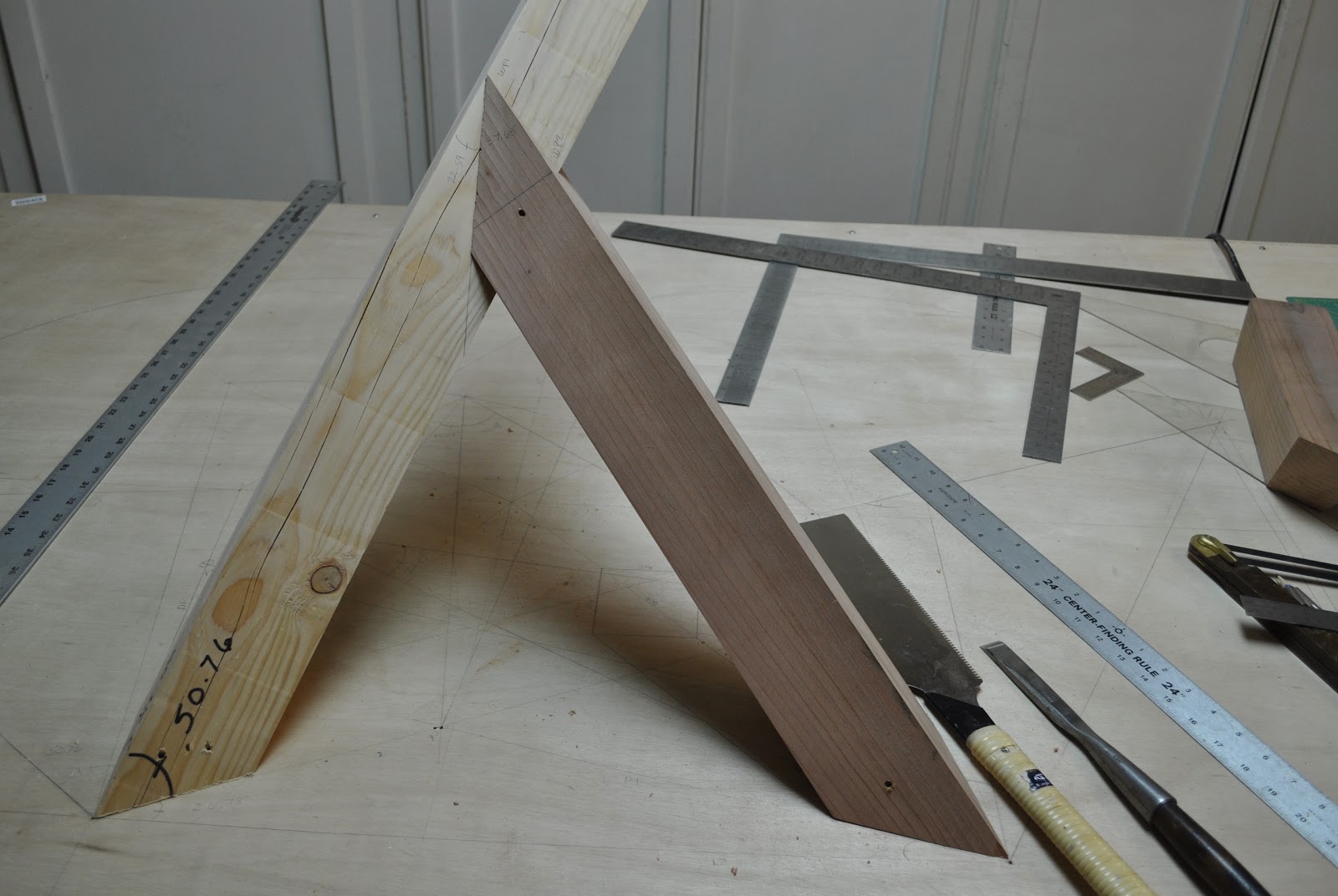
Here, the cut on Hip Rafter B looks like a witches cut. The two cuts from both sides of the hip rafter create the hidden line of the lower claw.

Here's an example cut, following the lines on two faces of the hip rafter and automatically following a cut line on a third face of the hip rafter. It's an easy way to tell if you laid it out correctly to begin with.


Transferring bevel angles from the drawing board.


Hip Rafter A slope Angle on Side Face = 50.76848°
Hip Rafter B slope Angle on Side Face = 45°
The hip rafter slope angle for the sides of the hip rafter rotated 45° from plumb is equal to the common rafter slope when the plan angle is 45°.
The hip rafter slope angle for the sides of the hip rafter rotated 45° from plumb is not equal to the common rafter slope when the plan angle is not at 45°.
Rotated Hip Slope Angle = arcsin (cos 26.56505° x cos 30) = 50.76848
or
Rotated Hip Slope Angle = arcsin (cos A7m x sin DD)
Rotated Hip Slope Angle = arcsin (cos 26.56505° x sin 60) = 50.76848
SB = arctan( sin(50.76848°) ÷ tan(50.76848°)) = 32.31153°
Saw Blade Bevel Angle on Hip Rafter A = 32.31153°
This saw blade bevel angle didn't work. I used 29.5°. Not sure what that's all about.
Miter Angle on Hip Rafter B = 45°
SB = arctan( sin(45) ÷ tan(45)) = 35.26439°
Saw Blade Bevel Angle on Hip Rafter B = 35.26439° = P2
Roof Eave Angle = 90.00000
SS = Main Rafter Slope Angle = 45.00000
S = Adjacent Rafter Slope Angle = 45.00000

DD = Main Plan Angle = 45.00000
D = Adjacent Plan Angle = 45.00000

DD = arctan (sin W ÷ (tan SS ÷ tan S + cos W)) = 45.00000

R1 = Hip Rafter Slope Angle = 35.26439
C5m Main Hip Rafter Backing Angle = 30.00000
C5a Adjacent Hip Rafter Backing Angle = 30.00000
Valley Sleeper Saw Blade Bevel Angle = 90° - (C5m + C5a) = 30.00000

P2m = Main Jack Rafter Side Cut Angle = 35.26439
90° - P2m = Main Roof Sheathing Angle = 54.73561
P2a = Adjacent Jack Rafter Side Cut Angle = 35.26439
90° - P2a = Adjacent Roof Sheathing Angle = 54.73561
A7m = 35.26439°
A7a = 35.26439°
Roof Eave Angle = 90.00000
SS = Main Rafter Slope Angle = 45.00000
S = Adjacent Rafter Slope Angle = 60.00000

DD = Main Plan Angle = 60.00000
D = Adjacent Plan Angle = 30.00000

R1 = Hip Rafter Slope Angle = 40.89339
C5m Main Hip Rafter Backing Angle = 20.70481
C5a Adjacent Hip Rafter Backing Angle = 48.59038
Valley Sleeper Saw Blade Bevel Angle = 90° - (C5m + C5a) = 20.70481

P2m = Main Jack Rafter Side Cut Angle = 22.20765
90° - P2m = Main Roof Sheathing Angle = 67.79235
P2a = Adjacent Jack Rafter Side Cut Angle = 40.89339
90° - P2a = Adjacent Roof Sheathing Angle = 49.10661
A7m = 26.56505°
A7a = 56.30993°


 Angles we need to layout the upper and lower claws on hip rafter B.
We still need a way to define the points B3-a or B3-b. This is the intersection on Hip Rafter B's bottom surface plane and the bottom of Hip Rafter A surface plane.


A5P = 26.71763°
90° – R1 = 37.65287°
DD = 55.39850°
90° – R5P = 43.14862°
P6 = 24.25247°
R3 = 90° – 55.69718° = 34.30282°
C2 = 21.52473°
90° – R2 = 64.47776°
C1 = 31.61865°
Q2 = 75.94701°
P3 = 28.90211°
Q4 = R4P – R3 = 22.85244° – 34.30282° = – 11.45038°
Kernel extracted from kernel, and re-drawn in standard position. This model clearly shows that the required angle to calculate Q4 is R4P.
Good thing I made the new “negative shape” model because I've been overlooking a most interesting thing in cross-section view. The projection of the skewed line to section is almost dead nuts 15°. Is it just a coincidence that an angle we see a lot of in plan crops up here, or is there a connection?
Sim – I think I’ve taken the Intersecting Hips as far as I can. No matter how I twist and turn the roof components there’s no way to fit the angles into a standard Hip-Valley-Common-Purlin type format. And it only makes the math and geometry more complicated.
Two other ways to solve the Intersecting Hips. We can use the lengthy linear algebraic formulas to find the dihedral angles-blade bevels between the planes. Given two blade bevels we can fill in the rest of the compound angle. ~ http://geocities.ws/web_sketches/angle_formula_catalogue/compound_angle_formulas.gif
Footprint Angle = arccos (tan Saw Blade Bevel × tan Blade Bevel for Adjoining Face)
Angle of Saw Travel = arccos (sin Blade Bevel for Adjoining Face ÷ cos Saw Blade Bevel)
Or we can exploit tetrahedra to find the dihedral angles between the intersecting planes. We know how to develop and/or calculate the Hip rafter footprints, the 57.68847° and 54.73561° planes and their traces in plan view – the DP lines. The following brings me back full circle to what I started with and abandoned as being too convoluted ...
Rather than drawing developed triangles I've attached is a rough draft of calculations (same as drawing as far as I’m concerned, the Javascript code is based on tetrahedron formulas).
Again we have our dihedral angles – same as returned by the linear algebra – and we can apply the Compound Angle Formulas. I’m a bit mystified by the last dihedral angle calc, why does it need to be subtracted from 180°? Intersecting planes form two pairs of supplementary dihedral angles so the answer is correct, but why didn't I have to find the supplements the first three angles?
I think that’s about as easy as this intersection is going to get and I’m content with where the math is at. The geometry, linear algebra and trigonometry return the same answers. Even the two seemingly disjunct upper and lower shoulder compound angles that had me scratching my head have been connected


Checking the footprint of hip rafter B to see if the hip rafter footprint matches the hip rafter footprint in plan view.
Upper and lower claw cuts of hip rafter B looks good.
Lower claw cut on hip rafter B.
Trying to find the intersection points of the bottom faces of the hip rafters.
Basic geometric layout for the rotated hip rafters.
Getting messy with all of the construction lines.
- 22.85223°
- 37.65303°
- 55.69718°
- 64.47776°
We can layout angles 22.85223° and 37.65303° using geometry, but we still need a geometric process to layout the other two angles.
We still need a way to define the points B3-a or B3-b. This is the intersection on Hip Rafter B's bottom surface plane and the bottom of Hip Rafter A surface plane.
We also need a way to define the points B4-a or B4-b. This is the intersection on Hip Rafter B's bottom surface plane and the bottom of Hip Rafter A surface plane.

Joe Bartok's diagrams and math notes for the Warlock cut.
What inspired this is two Valleys intersecting a principal
purlin (model included in one of the photos, also a drawing at the TF Guild
site ~ http://www.tfguild.org/downloads/publications/HV-III.pdf).
Each Valley has purlin related joints on one wing but a plumb cut where it’s
other side meets the opposing Valley, so we have two sets of angles
intersecting one another. The tetrahedron that connects the seemingly unrelated
angles is on Page #4 (a tetrahedron I thought was virtually
useless when I first found it). ~ http://geocities.ws/xpf51/LTFAPDF/VALLEY_SQUARE_CUT_ANGLES.pdf.
Here’s how I’m seeing the Warlock angles ...
R4P = 22.85244°A5P = 26.71763°
90° – R1 = 37.65287°
DD = 55.39850°
90° – R5P = 43.14862°
P6 = 24.25247°
R3 = 90° – 55.69718° = 34.30282°
C2 = 21.52473°
90° – R2 = 64.47776°
C1 = 31.61865°
Q2 = 75.94701°
P3 = 28.90211°
Q4 = R4P – R3 = 22.85244° – 34.30282° = – 11.45038°
Kernel extracted from kernel, and re-drawn in standard position. This model clearly shows that the required angle to calculate Q4 is R4P.
Good thing I made the new “negative shape” model because I've been overlooking a most interesting thing in cross-section view. The projection of the skewed line to section is almost dead nuts 15°. Is it just a coincidence that an angle we see a lot of in plan crops up here, or is there a connection?
Sim – I think I’ve taken the Intersecting Hips as far as I can. No matter how I twist and turn the roof components there’s no way to fit the angles into a standard Hip-Valley-Common-Purlin type format. And it only makes the math and geometry more complicated.
Two other ways to solve the Intersecting Hips. We can use the lengthy linear algebraic formulas to find the dihedral angles-blade bevels between the planes. Given two blade bevels we can fill in the rest of the compound angle. ~ http://geocities.ws/web_sketches/angle_formula_catalogue/compound_angle_formulas.gif
Footprint Angle = arccos (tan Saw Blade Bevel × tan Blade Bevel for Adjoining Face)
Angle of Saw Travel = arccos (sin Blade Bevel for Adjoining Face ÷ cos Saw Blade Bevel)
Or we can exploit tetrahedra to find the dihedral angles between the intersecting planes. We know how to develop and/or calculate the Hip rafter footprints, the 57.68847° and 54.73561° planes and their traces in plan view – the DP lines. The following brings me back full circle to what I started with and abandoned as being too convoluted ...
Rather than drawing developed triangles I've attached is a rough draft of calculations (same as drawing as far as I’m concerned, the Javascript code is based on tetrahedron formulas).
Again we have our dihedral angles – same as returned by the linear algebra – and we can apply the Compound Angle Formulas. I’m a bit mystified by the last dihedral angle calc, why does it need to be subtracted from 180°? Intersecting planes form two pairs of supplementary dihedral angles so the answer is correct, but why didn't I have to find the supplements the first three angles?
I think that’s about as easy as this intersection is going to get and I’m content with where the math is at. The geometry, linear algebra and trigonometry return the same answers. Even the two seemingly disjunct upper and lower shoulder compound angles that had me scratching my head have been connected
No comments:
Post a Comment
Note: Only a member of this blog may post a comment.