 |
| Kyle nailing up the double 2x12 ridge. Copyright Tim Uhler. |
Looking thru Tim Uhler's photos on the house he and Kyle are framing Bay Window Framing and Started the Main Roof prompted me to address Hip Rafter Roof Plane Alignment that Tim completely understands, but most carpenters struggle with. Probably the hardest roof framing planning point to get correct is on the hip rafter that nails to the wall on Bay Window Framing.
 |
| Bay Window Side Wal Hip Rafter Copyright Tim Uhler. |
Some people call it hip rafter drop, but it's just shifting the hip rafter plumb line to align with the intersection of the wall and having the same HAP as the common rafters.
 |
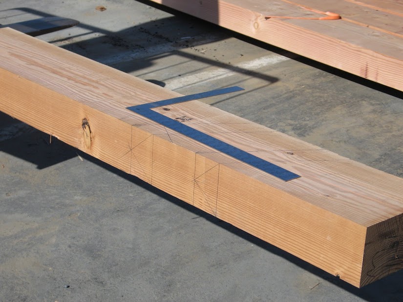
| Here's a picture of the double LVL hip rafter Tim's laying out with the hip rafter drop for roof plane alignment. |
I'll start off with some drawings of the geometry of the double LVL hip rafter to show the relationship between hip rafter roof plane alignment and hip rafter drop. Layout the standard hip rafter plumb line at the location of the seat cut for the hip rafter. Then layout the plumb line that is shifted half the thickness of the hip rafter. This applies to roofs with an 90° eave angle on equal pitched roofs only. From the plumb line that is shifted half the thickness of the hip rafter layout the new hip rafter seat cut line using the common rafter HAP that allows for roof plane alignment on un-backed hip rafters at the intersection of the wall line.


The intersection of hip rafter level line and the hip rafter plumb line that is shifted half the thickness of the hip rafter establishes the depth of the hip rafter backing cut line. This can be used for reference. You do not back out the hip rafter if you're using hip rafter drop.
The hip rafter level line is always laid out using Traditional Roof Framing Geometry and now I think it should be laid out on all hip rafters to show that you have a complete understanding of the hip rafter roof plane alignment.
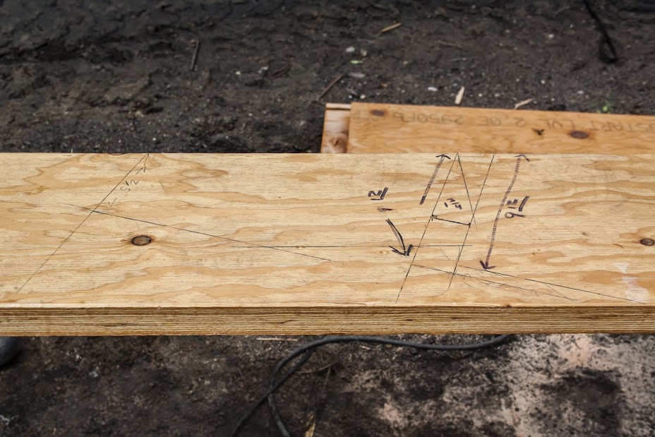
Here's some pictures of a 6x12 un-backed hip rafter with the plumb line shifted 2 3/4" , half the thickness of the 5 1/2" wide hip rafter. The common rafter HAP of 10" is laid out from the shifted plumb line for roof plane alignment with the common rafters.


This next drawing is for the Bay Window Hip Rafter located at the 135.00° Eave Angle. In this example the Bay Window Hip Rafter is 1 1/2" wide. The hip rafter plumb line will be shifted 5/16" of an inch to allow for the roof plane alignment.

The hip rafter that is nailed to the wall on a Bay Window Roof is referred to as the side wall hip rafter. The hip rafter plumb line will be shifted the thickness of the sidewall hip rafter (1 1/2").


Here's a couple of drawings showing the Hip Rafter Plumb Line Shift for unequal pitched roofs.
 |
| 8:12 & 10:12 pitch, 3 1/2" wide hip rafter, 90° eave angle |
 |
| 8:12 & 12:12 pitch, 3 1/2" wide hip rafter, 90° eave angle |
 |
| 8:12 & 12:12 pitch, 3 1/2" wide hip rafter, 120° eave angle |
Math for equal pitched roofs for Hip Rafter Plumb Line Shift
(1/2 of hip rafter width) * tan( 90° - plan angle) = Hip Rafter Plumb Line Shift dimension