Wednesday, April 30, 2014

Roof Framing Geometry Propositions – Axioms #3

Added a new Axiom to the Roof Framing Geometry Propositions. This one is for two rotated hip rafters for the angle on the bottom of the intersecting hip rafter.

Roof Framing Geometry Proposition – Axioms # 7:
A line from the intersection of the DP lines of two Hip Rafters, "a", to the hip rafter slope line "b" following the DP line, with a length equal to an arc length of the side face of the hip rafter lower claw length will determine point "c", for the angle on the bottom of the rotated hip rafter.


Unfolded pattern for the head cut on the rotated hip rafter intersecting the rotated hip rafter.

Monday, April 28, 2014

Roof Framing Geometry Proposition – Axioms #2

Using my Roof Framing Geometry Proposition – Axioms, it's like taking candy from a baby for laying out the geometry that defines the upper and lower claw angles on purlin rafters and jack rafters that tie into rotated hip rafters. Like Joe said,
The Mazerolle Code has been broken.


Purlin Rafter unfolded. You need 6 angles  and 2 dimensions to layout the unfolded template for the purlin rafter. 


Jack Rafter Unfolded.You need 3 angles  and 1 dimension to layout the unfolded template for the jack rafter.  The roof surface angles was obtained from the drawdown method of the roof surface.


Joe Bartok's 2014 Studies

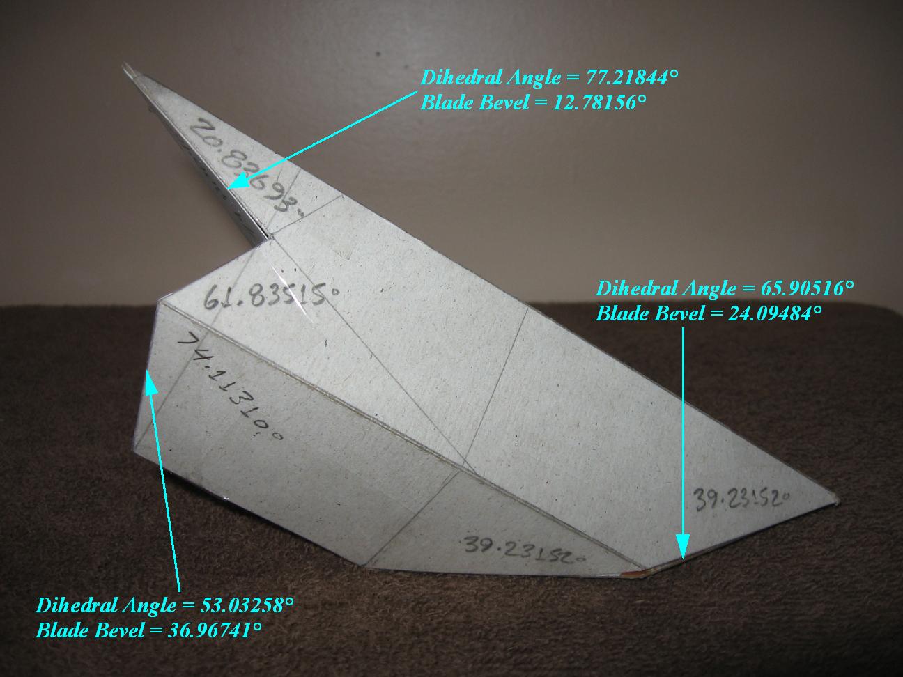
Here's a picture of the studies for the winter of 2014 by Joe Bartok. Joe's studies include the Golden Rhombus, Golden Rhombus Parallelogram, Trèteaux Angles -- Trestle Angles -- trèteau à devers, Devers De Pas -- DP Line, trait carré -- TC, when hips collide, rotated rafters, rotated hip rafters, Warlock Cut, Warlock Rhombic, Non-Rectangular Sections, Pentahedron and Non-Rectangular Sections, Trirectangular Tetrahedron, Raccord--Origami 3D models all with upper and lower claw angles.

  There's been a lot of trigonometry in Joe's studies, but there's also been a lot of geometry in his drawings leading up to his cardboard models. It was from his geometry, that he developed on his own, without looking at the French or German books, that some of my Roof Framing Geometry Proposition – Axioms were based on. The German Dachstuhlbau geometrie method or the 'Art du Trait', developed in the 13th century by the French are all based on stereotomtic principles developed 500+ BC for the stone masons. Whether we're using the Basiswissen Dachfläche Ausmittlung or Shiftungen method developed by the German Zimmerman or the Art Du Trait, “Compagnonnage” system in France by the French Compagnons, both methods are for developing the intersection of 3D planes drawn in 2D space just like Joe's geometric drawings.

Quote from Joe
_____________________________________________________________


Other than glimpses on the Internet I’ve never read or studied the books by Louis Mazerolle et al. For sure the timber framers and carpenters of the past (and some today) would have been aware of and understood the reference lines and planes required to lay out their work. But I've wondered if it was it done to an organized, universal set of rules (http://sbebuilders.blogspot.ca/2014/04/roof-framing-geometry-propositions.html)? Or were they locating the nodes or intersects of lines and connecting the points (like I did for the Warlock Cuts and offset rafters)?

My roof framing geometry horizons have certainly expanded these last two months, lots of new ways to look at the geometry. What's really cool about this is that the seemingly "different" intersections all tie into or are related to one another. _____________________________________________________________


Sunday, April 27, 2014

Principles Du Devers Traite A LA Sauterelle

I was checking my Roof Framing Geometry Proposition – Axioms against Patrick Moore's Principles Du Devers Traite A LA Sauterelle drawing on this page at Historical Carpentry . My Roof Framing Geometry Proposition – Axioms work with his techniques for Devers De Pas, but mind require a rafter depth to determine some of the lines. Patrick's techniques are in theory only in that drawing, showing the principles of the art of line. No width or depth of the rafters are required for his drawing.
Drawings showing the difference between the Principles Du Devers Traite A LA Sauterelle techniques and the techniques for using the Roof Framing Geometry Proposition – Axioms.

Sauterelle means using a bevel square to transfer the angles from the geometric layout to the timber.

Drawing showing the basic geometric layout of the roof. In this example I used a 90° eave angel with equal profile rafter slopes of 45°.


 Adding the DP lines for the rotated hip rafter.

Establishing the vertical plane tilt of the hip rafter.


Showing the triangle that represents the plane of the rotated hip rafter.

3D drawing of the rotated hip rafter with the vertical plane tilt drawn in 2D and 3D.

Developing the triangle that represents the plane of the rotated hip rafter for both sides of the hip rafter.

Showing the location of the plumb to the earth jack rafter and purlin rafter parallel to the plate line.

Drawing showing the theory used by Patrick for the upper and lower claw angles of the jack rafter.

3D drawing of the hip rafter with the jack rafter upper and lower claw angles dimensioned.

Drawing showing my Roof Framing Geometry Proposition – Axioms versus the theoretical way of laying out the geometry for the jack rafter upper and lower claw angles.

Drawing showing my Roof Framing Geometry Proposition – Axioms for laying out the geometry for the jack rafter upper and lower claw angles.
 Drawing showing the theoretical way of laying out the geometry for the jack rafter upper and lower claw angles.

 3D drawing of the purlin rafter. 


Drawing showing my Roof Framing Geometry Proposition – Axioms versus the theoretical way of laying out the geometry for the purlin rafter upper and lower claw angles.

Drawing showing my Roof Framing Geometry Proposition – Axioms for laying out the geometry for the purlin rafter upper and lower claw angles.
 Drawing showing the theoretical way of laying out the geometry for the jack rafter and purlin rafter upper and lower claw angles.


Using Trigonometry to check the geometry for Sauterelle Angles
Initial Given Values:
Hip Rafter Section Profile = Square
Roof Eave Angle = 90.00000
SS = Main Rafter Slope Angle = 45.00000
S = Adjacent Rafter Slope Angle = 45.00000
DD = Main Plan Angle = 45.00000
D = Adjacent Plan Angle = 45.00000
R1 = Hip Rafter Slope Angle = 35.26439
C5m Main Hip Rafter Backing Angle = 30.00000
C5a Adjacent Hip Rafter Backing Angle = 30.00000
P2m = Main Jack Rafter Side Cut Angle = 35.26439
90° - P2m = Main Roof Sheathing Angle = 54.73561
P2a = Adjacent Jack Rafter Side Cut Angle = 35.26439
90° - P2a = Adjacent Roof Sheathing Angle = 54.73561
Hip Rafter Section Profile View Rotation Angle = 45° 

Hip Rafter Foot Calculations by Joe Bartok
FA-DP = Hip Rafter Footprint Angle in Plan View = arctan (sin 35.26439° × tan 45°) = 30.00°

R1-DP = Hip Rafter Slope Angle on DP Shoulder = arccos (cos 35.26439° × cos
30.00°) = 45.00°

Vertical Plane Rotation Angle from Plumb for Tilted Hip Rafter on DP Line
R1V-DP = arctan(1 ÷ (tan(R1) ÷ sin(FA-DP)))
R1V-DP = arctan(1 ÷ (tan(35.26439°) ÷ sin(30.00°))) = 35.26439°


Saturday, April 26, 2014

Warlock Rhombic

Joe Bartok's study on 3 rotated intersecting rafters using , Euclidean geometry (geometry in flat space, 2D drawings that helped develop the Roof Framing Geometry Proposition – Axioms) and analytical geometry (geometry on a coordinate plane using trigonometry).
_______________________________________________________________
warlock_rhombic_nr_solution.pdf

warlock_rhombic_javascript_solution.pdf

– find the angles and dimensions to DP lines, complete calculations with Law of Cosines
– solve as for rectangular section with Compound Angle Formulas, apply bevel with Non-Rectangular Section calculator
– solve angles with only the Roof Framing and Joinery Calculator
_______________________________________________________________