Wednesday, October 30, 2013

European Task Model #2


This European Task model is from Tony McGartland from South West College, Omagh. N.Ireland, who helps train the UK/Ireland apprentice carpenters for the WorldSkills Carpentry Competition. While going thru this geometric exercise I discovered a real easy way to draw out crossing rafters, Saint Andrew's Cross Rafters or any rafters perpendicular to the roof surface like purlin rafters.


Here's the ground plan for the task model with the profile rafter and the heights-locations of the crossing rafters.


Added the hip rafter profile.


This task model is similar to the Schräge Sparren model where the top edge of the hip rafter is beveled in one direction only.

Here I developed the roof surface.


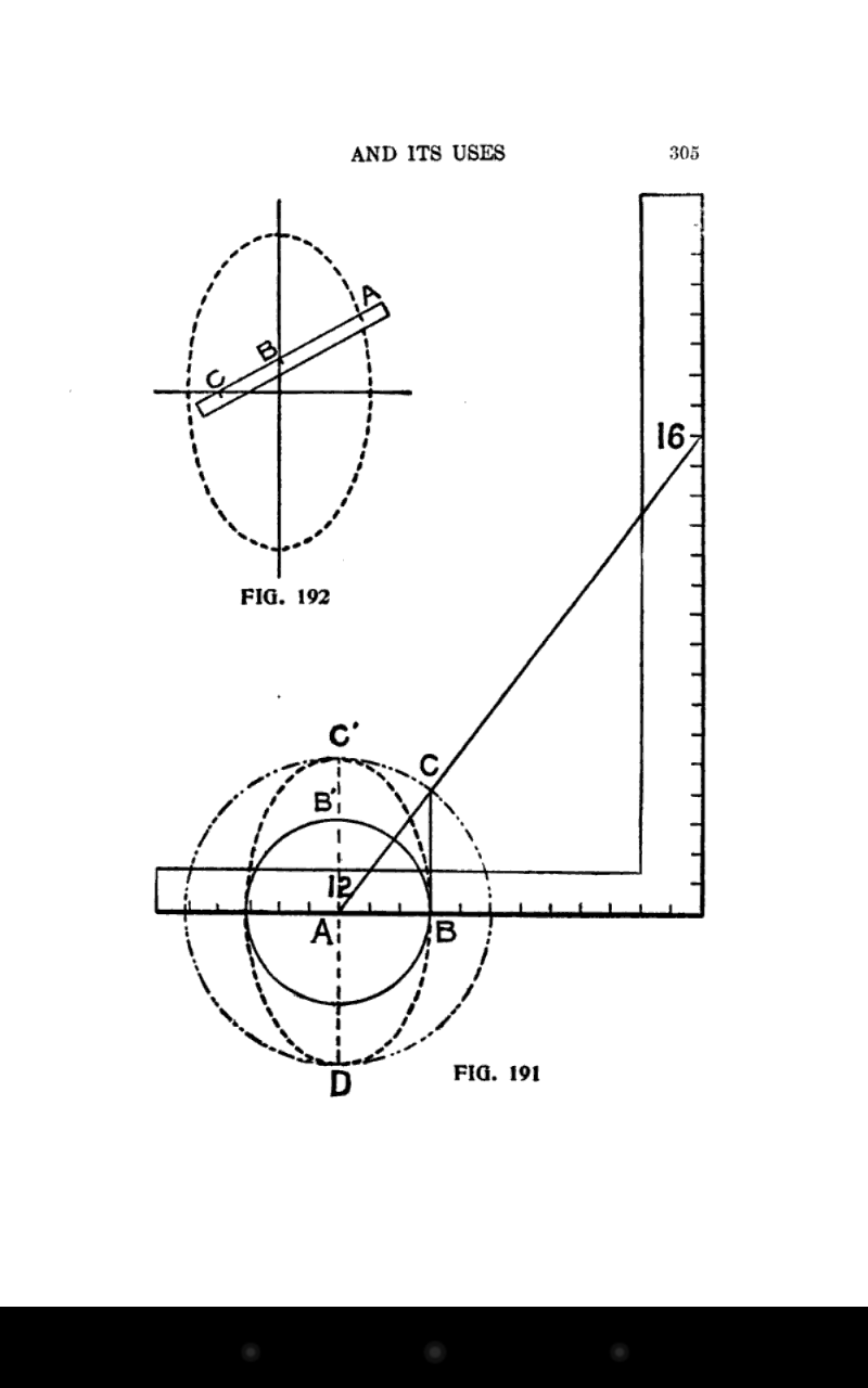
In this next drawing I drew out the backing angle for the hip rafter and I also used the rotated rafter block to determine the dimension of the internal edge of the hip rafter on the real roof surface. Then I drew some perpendicular  lines to the crossing rafter on the roof surface to develop the miter angle of the crossing rafter.

The crossing rafters are 40cm x 40cm. Use a 40cm x 40cm rafter block perpendicular to the hip rafter backing triangle to determine the dimension for the internal edge of the hip rafter on the roof surface that is drawn parallel to the edge of the hip rafter on the roof surface.


This is a 3D drawing of the crossing rafters. When two rafters are perpendicular to the roof surface, the miter angle on the side of the crossing rafters is 90°.


Here I'm checking the miter angle of the crossing jack rafter at the foot of the crossing rafter where it intersects the hip rafter.

Here's a 3D drawing of the two crossing rafters as they intersect at the hip rafter.


Checking the miter angle of the crossing jack rafter at the intersection of the hip rafter.


Drawing of the king common rafter at the intersection of the hip rafters.

3D drawing showing the crossing rafters that are rotated into the roof surface.


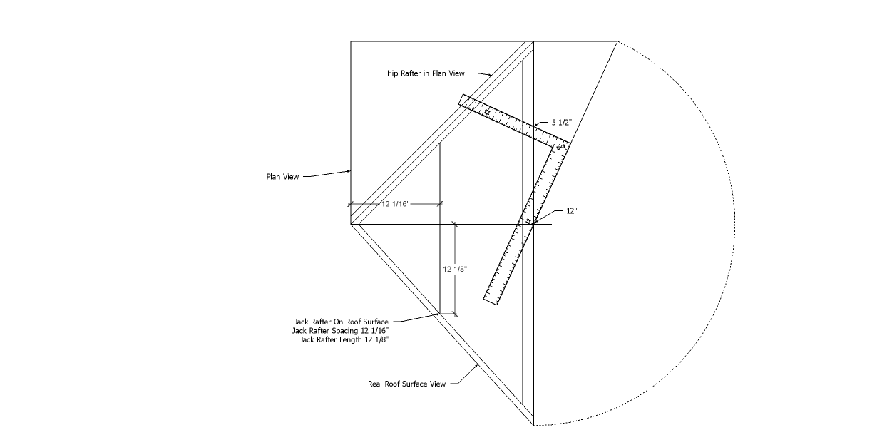
These next three drawings are priceless. Over the last 5 months, that I've been studying the Traditional layout techniques, the French & German Traditional Layout Books do not show this technique of placing the lumber over the roof surface drawing and drawing perpendicular lines at the edge of the hip rafter and perpendicular lines at the internal edge of the hip rafter on the roof surface. These  perpendicular lines automatically develop the correct miter and bevel angles for the rotated rafters. No need to draw perpendicular lines off to the side of the roof surface to develop the true shape of the crossing rafter.


Tuesday, October 29, 2013

European Task Model #1

Tony McGartland from South West College, Omagh. N.Ireland, who helps train the UK/Ireland apprentice carpenters for the WorldSkills Carpentry Competition sent me a couple of the European Task Models. These task models look like fun projects. This first task model has the typical irregular hip rafter on an eave angle of 105° with jack rafter with claws. There's also one rafter plumb to the earth and skewed from the plate line.


One thing that's confusing in the task model drawing is the color of the orange - brown rafter on the right side of the drawing. I don't think it should have been the color orange-brown like the hip rafter, because it's just  a rafter that's plumb to the earth and skewed from the plate line. It's a Schräge Sparren and has a top bevel edge, but it's not a hip rafter in this drawing. Hip rafters have a dihedral angle triangle and Schräge Sparren  do not. It's similar to what we call a gable end prow rafter. But the Schräge Sparren top edge is beveled. 


Plan View of the Task Model


Rafter Profiles developed from Plan View and the Jack Rafter Claw Angles developed from the prism plane geometry.

The task model wasn't clear on the tail slope angle, unless you speak Danish, so I used a tail slope angle 105° to develop the Hexenschnitt -- The Witches Cut on the hip rafter and the Schräge Sparren.


Sunday, October 27, 2013

Historical and Descriptive Square Used by the Earliest Builders

Quote From

Radford's cyclopedia of construction: carpentry, building and ..., Volume 8

 edited by William A. Radford, Alfred Sidney Johnson


Historical and Descriptive
Square Used by the Earliest Builders.—
The Greeks, who were an inventive people, and who were apt to ascribe to themselves more credit than was really their due, in the way of inventions and discoveries, lay claim to be the inventors of the instrument. Pliny says that Theodorus, a native of the island of Samos, was the inventor of the square and the level. Theodorus was an artist of some note, but it is evident that the square and level, in some form or other, were used long before his time, even in his own country, for some of the finest temples in Athens and other Grecian cities had been built long before his day; and the Pyramids of Egypt were hoary with age when he was in swaddling clothes.
Thus the claims made by the Greeks, to have been the originators of these two most important tools—the square and the level—we must admit, are hardly borne out under the best of authentic evidence. Indeed, the "square," as a constructive tool, must of necessity have found a place in the "kit" of the earliest builders. Evidences of its presence have been found in the ruins of prehistoric nations, and are abundant in the remains of ancient Petra, Nineveh, Babylon, Etruria, and India. South American ruins of great antiquity in Brazil, Peru, and other places, show that the unknown races that once inhabited the South American Continent, were familiar with many of the uses of the square. Egypt, however, that cradle of all the arts, furnishes us with the most numerous, and, perhaps, the most ancient evidences of the use of the square; paintings and inscriptions on the rock-cut tombs, the temples, and other works, showing its use and application, are plentiful. In one instance, a whole "kit" of tools was found in a tomb at Thebes, which consisted of mallets, hammers, bronze nails, small tools, drills, hatchets, adzes, squares, chisels, etc.; one bronze saw and one adze have the name of Thothmes III, of the 18th dynasty stamped on their blades, showing that they were made nearly 3,500 years ago. The constructive and decorative arts at that time were in their zenith in Egypt, and must have taken at least 1,000 years to reach that stage. Consequently, the square must have been used by the workmen of that country, at least, four thousand years ago.
The British Museum contains many tools of pre-historic origin, and the square is not the least of them. Herculaneum and Pompeii contribute evidences of the importance of this useful tool. On some of the paintings recently discovered in those cities, the different artisans can be seen at work in their own workshops, with their work benches, saw-horses, tools, and surroundings,  much about the same as we would find a small carpenter shop of today, where all the work is done by hand; the only difference being a change in the form of the tools, which, in some instances, had been better left as these old workmen devised them.
It can make no difference, however, to the modern workman, as to when or where the square was first used; suffice to know, that at present, we have squares immensely superior to anything known to the ancients, and it may be added, that so perfect has the machinery for the manufacture of steel squares (1909) become, that a defective tool is now the exception. Of course this relates to the products of manufacturers of repute, and not to the cheap squares, or to those said to be first class, that were made ten or fifteen years ago. The tool we recommend in this book is the best made, both as to quality of material, accuracy of workmanship, and amount of useful matter on its faces.


The following images are not from volume 8, but the book I wanted in printed form.


Saturday, October 26, 2013

Full Length Roof Framer the Missing pages

I've cut over a 1,000 roofs from the Full Length Roof Framer by A.F.J Riechers and the one thing that has always bothered me was the explanations - drawings in the book. I think the following drawings should have been included in the Full Length Roof Framer as well as the book Simplified Roof Framing by Wilson & Werner.


Missing pages from both books

With a simple drawing showing the roof plane alignment point it would have been a lot easier to understand the hip rafter backing angle and depth.


With a simple drawing showing a jack rafter layout board it would have been a lot easier  to find the length of the first jack rafter.


With a simple drawing showing a standard roof framing kernel it would have been a lot easier  understand bastard hip roofs.


With a simple drawing showing the hip rafter shift - offset at the eave line it would have been a lot easier  understand bastard hip roofs.


With a couple of simple drawings showing showing the plumb line shift for jack rafters it would have been a lot easier  understand jack rafter side cuts.


Sunday, October 20, 2013

Roof Framing Base Knowledge #1

I finally had the time to have Brian and Erik draw a Jack Rafter Layout Board and show them how to layout a hip rafter correctly. Also, I had them cut the jack rafter back bevels (side cuts) with a hand saw. It might be the first time in 60-80 years that a stick framer carpenter in California has cut any rafter bevel with a hand saw.

Jack Rafter Layout Board


The jack rafter layout board allows you to draw out the real roof surface of the roof. On this house we had to align our rafters with the open web floor joist and it resulted in 4 different lengths for the first jack rafter length at each of the 3 hip rafters. Once you draw the jack rafter layout board you use the run of the jack rafter in plan view to draw out the jack rafter in the roof surface view to find the dimension of the jack rafter.


Drawings of jack rafter back bevel layout.


Here's Brian and Erik cutting the jack back bevels with a handsaw. It's important to know how to layout a jack rafter head cut. Once you layout and cut a jack rafter back bevel angle you'll have a better understanding of how the compound angles are developed using a skill saw.


The Seven simple steps to layout the hip rafter correctly.
  1. Hip Rafter Plumb Line
  2. Hip Rafter Level Line
  3. Hip Rafter Shifted Plumb Line
  4. Hip Rafter Backing Depth Line
  5. Roof Plane Alignment  Point
  6. Hip Rafter Seat Cut Line
  7. One Length Method for Hip Rafter Head Cut Line.


One Length Method for Hip Rafter Head Cut Line.
Mark off the hip rafter head cut plumb line from the Roof Plane Alignment Line. 

The hip rafter run to the ridge was 71 1/2". With a 5 1/2" - 12 pitch the hip rafter length was 106 5/16" . Mark off the  106 5/16" from the Roof Plane Alignment Line to mark the hip rafter head cut line. 


Example of the One Length Method with only the necessary lines to cut the hip rafter. The skill saw cuts at the seat of the hip rafter develop the correct angles to locate the theoretical hip rafter plumb line at the corner of the plate line.