Tuesday, February 26, 2013

Hexagonal Roof Framing Plan with dévers de pas & trait carré

dévers de pas & trait carré model with lumber left over from our previous jobs.
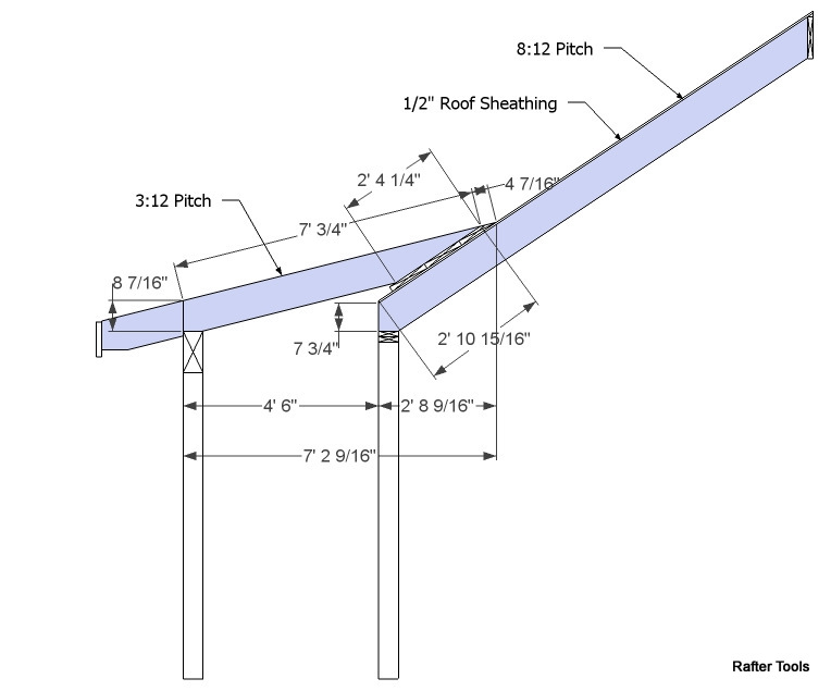
Arêtiers à dévers --> Hip at tilt

Hexagonal Roof Plan with skewed rafters rotated into the roof surface plane.


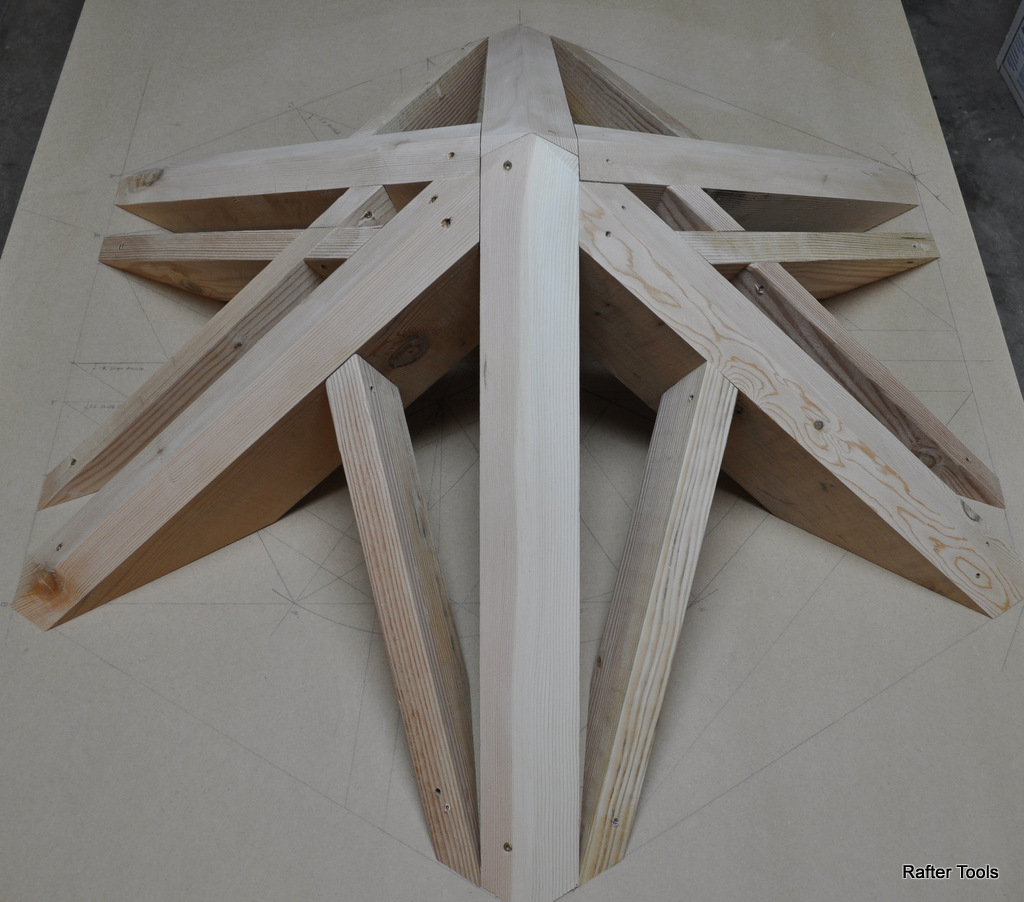
Geometry development photos

Rafter Tools Calculations
Crossing Valleys


main_plan_angle = 60.00000
main_pitch_angle = 33.69007
skewed_plan_angle = 60.00000
adjacent_pitch_angle = 49.10661

main_hip_angle = 30.00000
main_backing_angle = 16.10211
main_jackrafter_angle = 25.65891

skewed_hip_angle = 30.00000
skewed_jackrafter_angle = 25.65891
skewed_sheathing_angle = 64.34109

k2 = 51.31781
k9 = 73.89789

k1 miter angle = 20.29440
k2 bevel angle = 51.31781
k3 saw blade bevel angle = 36.90433
k4 horizontal plane rotation angle = 8.21321
k4 Vertical plane rotation angle = 17.48017
R1 valley rafter slope angle = 30.00000
k5 valley rafter rotated slope angle = 31.00272
k8 hip rafter housing angle = 12.51983

rafter rotated Level Foot Miter angle = 31.00272
rafter rotated level bevel angle = 64.34109
rafter rotated level Saw Blade Bevel angle = 13.89789

rafter rotated Foot Miter angle = 36.48664
rafter rotated bevel angle = 64.34109
rafter rotated Saw Blade Bevel angle = 21.11790

Ridge Miter angle = 36.48664
Ridge bevel angle = 64.34109
Ridge Saw Blade Bevel angle = 21.11790

rafter rotated crossing Miter angle = 0.00000
rafter rotated crossing bevel angle = 51.31781
rafter rotated crossing Saw Blade Bevel angle = 38.68219


Rafter Tools Calculations
Skewed Rafter


main_plan_angle = 60.00000
main_pitch_angle = 33.69007
skewed_plan_angle = 45.00000
adjacent_pitch_angle = 33.69007

main_hip_angle = 30.00000
main_backing_angle = 16.10211
main_jackrafter_angle = 25.65891

skewed_hip_angle = 25.23940
skewed_jackrafter_angle = 39.76216
skewed_sheathing_angle = 50.23784

k2 = 65.42106
k9 = 73.89789

k1 miter angle = 17.61144
k2 bevel angle = 65.42106
k3 saw blade bevel angle = 23.55495
k4 horizontal plane rotation angle = 10.30485
k4 Vertical plane rotation angle = 22.77022
R1 valley rafter slope angle = 25.23940
k5 valley rafter rotated slope angle = 27.13381
k8 hip rafter housing angle = 7.22978

rafter rotated Level Foot Miter angle = 27.13381
rafter rotated level bevel angle = 50.23784
rafter rotated level Saw Blade Bevel angle = 20.78042

rafter rotated Foot Miter angle = 40.93373
rafter rotated bevel angle = 50.23784
rafter rotated Saw Blade Bevel angle = 32.15294

Ridge Miter angle = 40.93373
Ridge bevel angle = 50.23784
Ridge Saw Blade Bevel angle = 32.15294

rafter rotated crossing Miter angle = 0.00000
rafter rotated crossing bevel angle = 65.42106
rafter rotated crossing Saw Blade Bevel angle = 24.57894


Saturday, February 23, 2013

WorldSkills 2011 Carpentry Competition Model Geometry

The WorldSkills 2011 Carpentry Competition Model - Project was based on a pentagon ground plan with a sloping ridge. The Model - Project also has valley rafters rotated into the roof surface plane supporting a dormer.
Ground Plan of Model


Ground Plan showing post and roof beam location.


Roof Plan


The sidewall length of the pentagon was given as 1000 mm. There are a number of different ways to layout the pentagon. However, I suggest you familiarize yourself with the use of using the tan of the angle and multiplying the tan of the angle by 10 and taking 10" on the other end of the framing square.  


To find the circumscribed radius, that is also the hip rafter run dimension, you can use 
sidewall  ÷ (sin(180° ÷ number sides) x 2) = sidewall multiplier.

sin(180° ÷ 5) x 2 = 1.175571
 1000mm  ÷ 1.175571 = 850.6504 mm circumscribed radius
or
39.3701" = 1000mm
 39.3701 ÷ 1.175571 = 33.49019" circumscribed radius


The roof framing geometry should start off by drawing the common rafter slope angle of the pentagon. You could use an calculator to find the rise, line BC, or draw out the line AC at an 35° angle using a metric framing square or possibly a large protractor. The ridge of the model is slopping, so we need to find the height at H. Line BE is parallel to eave line / gutter line, the height at F is the same as the height at C. By drawing a line from D thru F it will locate the point H. Which is the total height of the slopping ridge. Triangle CFH gives an slope angle of 12.20919°.


Next, we need to lay out the  real roof surfaces. The line A1 - A1' is equal in length to the line AC. True Common Rafter Length. The line HR-A1' is equal in length to the True Length of  the Hip Rafter. From A1' draw a perpendicular  towards F' the length of the line BE. You should swing an arc from center point D with the radius equal to DF, so that the line A1'-F' intersect with the arch. Draw a line from D thru F' towards H'. Then swing an arc from center point D using the radius equal to DH. 


In this next drawing there are two examples of drawing the hip rafter backing angles. For all hip rafter backing  triangles the line at D is perpendicular to the hip rafter run line and the line at E is always drawn perpendicular to the hip rafter length line. Point G is located from the radius ED, with center point D.


Next develop the devers de pas for the Valley Rafters Crossing each other. These valley rafters are rotated into the roof surface plane. First develop the hip rafter right triangle BGH in the drawing below.  Next draw the line LD perpendicular to line AB that intersects line BG at D. Then draw the line DF perpendicular to line BG. Line DK is equal in length to DF and is perpendicular to line LD. Draw the line LK. Next draw a line that is perpendicular to line LK.Continue line LD to intersect the line KM . The line KM is the TC line. From E, draw a line to M. The line EM is the DP line, that will establish the rafter's miter and bevel angle.

In this next drawing the point P is the intersection of line BG and EM. From point P draw a line to F. Transfer the lines between point F,P,E and D to the side of the drawing to establish the miter angle of the rafter that's rotated into the roof surface plane. We need to establish the point Q and V for the miter angle.

Draw the line DF' perpendicular to line ED, then draw the line EF'. Next strike an arc from center point D the length of DF . Strike an arc from center point E the length of EF'. Where the two arcs intersect , point Q, draw the line QP and EQ. Draw another perpendicular line to EQ that intersects at point P. This will form the line VP. The angle VPQ is the miter angle of the valley rafter rotated into the roof surface plane.


Rafter Tools Devers De Pas Calculations 

Main Plan Angle = 54.00000
Main Pitch Angle = 35.00000
Skewed Plan Angle = 54.00000
Adjacent Pitch Angle = 43.94255

Main hip Rafter Angle = 29.53068
Main Hip Rafter Backing Angle = 19.70271
Main Jack rafter Side Cut Angle = 30.75894

Skewed Hip Angle = 29.53068
Skewed Jack Rafter Side Cut Angle = 30.75894
Skewed Roof Sheathing Angle = 59.24106

k2 = 61.51788
k9 = 70.29729

k1 Valley Rafter Peak Miter Angle = 22.16679
k2 Valley Rafter Peak Bevel Angle = 61.51788
k3 Valley Rafter Peak Saw Blade Bevel Angle = 26.67730
k4 Valley Rafter Horizontal Plane Rotation Angle = 10.00996
k8 Valley Rafter Vertical Plane Tilt Angle = 19.16497
R1 Valley Rafter Slope Angle = 29.53068
k5 Valley Rafter Rotated Slope Angle = 31.03562
k6 Valley Rafter Vertical Plane Tilt = 19.16497
k7 Hip Rafter Housing Angle = 10.36571

Valley Rafter Foot Miter Angle = 39.17428
Valley Rafter Bevel Angle = 59.24106
Valley Rafter Saw Blade Bevel Angle = 24.76747

Valley Rafter Ridge Miter Angle = 39.17428
Valley Rafter Ridge bevel Angle = 59.24106
Valley Rafter Ridge Saw Blade Bevel Angle = 24.76747

Valley Rafter Foot Level Cut Miter Angle = 31.03562
Valley Rafter Foot Level Cut Bevel Angle = 59.24106
Valley Rafter Foot Level Cut Saw Blade Bevel Angle = 17.05818


Valley Rafter Cross Cut Miter Angle = 0.00000
Valley Rafter Cross Cut Bevel Angle = 61.51788
Valley Rafter Cross Cut Saw Blade Bevel Angle = 28.48212


Saturday, February 16, 2013

WorldSkills dévers de pas & trait carré

To compete in the World Skills International Competition for carpentry you must have a complete understanding of the roof framing geometry of dévers de pas & trait carré.

dévers de pas  = DP line
trait carré  = TC line or TP line

Google's translations of anything with the words dévers de pas or trait carré still sucks.

Google translations from this PDF file are just terrible.

Valley Rafter Edge Bevel Angle

Original French Text:

L’angle formé par la ligne partant du sommet pour joindre le dévers de pas à sa rencontre
avec l’axe du faîtage en plan donne l’angle de coupe sur la face déversée. La mise en herse de la
hauteur 12 à la rencontre de l’axe du faîtage donne l’angle et la longueur sur la face déversée
recevant les empannons.


Google English translation:


The angle formed by the line from the top to reach the slopes of not meeting its
with the axis of the ridge in plan is the cutting angle on the face spilled. The implementation of the harrow
height 12 to meet the ridge axis gives the angle and length of the face spilled
Jack rafter receiving.

dévers de pas --> slopes of not

dévers de pas  should translate to:
dévers de pas --> the angle of the projection line 

dévers de pas --> The slope of a piece of wood is warping or sloping.

dévers  --> cant ... tilt
dévers  --> cant .. this is not plumb.

definition of 1798 French Academy dictionary
Cant, is also a noun. "We must mark the timber along its slope,"that is to say, according to its slope or warping.

 trait carré  -->should translate to:
 trait carré  -->  a line that cuts another line at right angles or a perpendicular line.


Tim Moore's blog on Stereotomy
The art of representing objects in section, elevation and plan in order to cut them out. - Louis Mazerolle


Tim's drawing's on this page are a good start on understanding the DP & TC lines.

http://stereotomy-blog.blogspot.com/2011/09/devers-de-pas-2.html


or Chis Halls blog for those of you that are very advanced in the theory of timber framing by Louis Mazerolle.

http://thecarpentryway.blogspot.com/2010/03/following-mazerolle-theorie-des-devers.html


Here are a couple of examples of the timbers/rafters rotated into the roof surface plane that use the DP line to find the slope angle of the rafter and the tilt of the rafter. 


Real world examples of rotated valleys

Roof rafter support post and rafters forming a maze of  angles.


Valley rafter rotated into the roof surface plane, long before we were born.

Some more models of the rotated valleys.

Valley rafter rotated perpendicular to roof surface. The jack rafter side cuts have a zero degree miter angle.


Rotated valleys on an polygonal plan with a sloping ridge and prow rafters on the end of the gable roof.


Close up of the valley's foot print and the jack rafters  running at different  directions. One set of jack rafters running  perpendicular to the ridge and the other set running perpendicular to the gutter line.


dévers de pas
Simplified


To simplify the DP line geometry I'm using a square rectangle plan with an equal pitched roof slope in this example. The valley rafters that are rotated into the roof surface plane are crossing each other. 


Equal Pitched Roof Slope
8:12 = 33.69007


Develop the hip rafter right triangle BGH. The rise of the roof is 8". Draw GH 8" in length and perpendicular to line BG. Then draw line HB, that represents the true length of the hip rafter.

Next draw the line LD perpendicular to line AB that intersects line BG at D. Then draw the line DF perpendicular to line BG. Line DK is equal in length to DF and is perpendicular to line LD. Draw the line LK. Next draw a line that is perpendicular to line LK.Continue line LD to intersect the line KM . The line KM is the TC line. From E, draw a line to M. The line EM is the DP line, that will establish the rafter's miter and bevel angle.

The line TC is always perpendicular to the roof surface. Laying a framing square on the roof surface from point L thru point D will locate the point M. 


In this next drawing the point P is the intersection of line BG and EM. From point P draw a line to F. Transfer the lines between point F,P,E and D to the side of the drawing to establish the miter angle of the rafter that's rotated into the roof surface plane. We need to establish the point Q and V for the miter angle.


Draw the line DF' perpendicular to line ED. Next strike an arc from center point D the length of DF' . Then draw the line DF. Draw the line PF.   Strike an arc from center point P the length of PF. Strike an arc from center point E the length of EF'. Where the two arcs intersect , point Q, draw the line QP and EQ. Draw another perpendicular line to EQ that intersects at point P. This will form the line VP. The angle VPQ is the miter angle of the valley rafter rotated into the roof surface plane.


This next drawing shows how to develop the bevel angle of the valley rafter rotated into the roof surface plane. The bevel angle is 2 * the Jack Rafter Side cut Angle.


The geometry shown on this page can be used to develop the dévers de pas,  DP line, for any roof eave angle, like an pentagon (108°), hexagon (120°), octagon (135°) etc... , when the valley rafters are rotated into the roof surface plane.


Sunday, February 10, 2013

World Skills International Competition Roof

After looking at a couple of Joe Bartok's cardboard roof models yesterday it gave me an idea for a roof that could be used in the World Skills International Competition  in Europe. This World Skills International Competition Roof  would have an hexagonal foot print with an star foot print extending from two sides.


This  hexagonal  roof has hip rafters that are both a hip and a valley rafter at the same time. It also would have one roof slope angle that can only be calculated from the geometry of the roof. In my example  I've used an 5:12 pitch as the main roof pitch with the adjacent hexagonal eave angle having an 12:12 roof pitch.


If the World Skills International Competition judges are expecting perfect cuts from the competitors, then maybe they could use my Rafter Tools apps to check the accuracy of the  competitors geometry. I tested my new and improved plan angle formula on this hexagonal roof and it returned the correct plan angles for the 3 different roof pitch angles with the 3 different eave angles.


Just found these drawing for the World Skills International Competition in 2010 & 2011. The drawing is showing a roof with the purlin rafter projecting under the hip rafter. The student would have to know how to geometrically draw out the purlin lip cut angle. The World Skills International Competition allows carpenters to use calculators. Maybe the World Skills International Competitors could use the Rafter Tools calculator?


Here are a couple of drawings showing how to draw out the purlin lip cut angle.


Saturday, February 9, 2013

CutIn Dormer Shed Roof Rafter Calculator


This CutIn Dormer Shed Roof Rafter Calculator will return the roof framing trigonometry & geometry details for:

  1. Dormer Shed Roof Rafter Length
  2. Dormer Shed Roof Miter Angle (Rake Cut Angle)
  3. Dormer Shed Roof Run
  4. Main Roof Rafter Intercept Length
  5. Dormer Intersect Length For Lapping Rafters
  6. Intersecting Roof Slope Angle


Intersecting Roof Slope Angle = arctan((Main Pitch - Dormer Pitch) ÷ 12) 
Dormer Height = Dormer Height Above Main Roof + Dormer HAP
Main Roof Rafter Intercept Length = (Dormer Height ÷ tan(Intersecting Roof Slope Angle) ) ÷ cos(Main Roof Pitch Angle)
Dormer Run = Dormer Height ÷ tan(Intersecting Roof Slope Angle)
Dormer Rafter Length = Dormer Run ÷ cos(Dormer Roof Pitch Angle)
Dormer Miter Cut Angle =  Main Roof Pitch Angle - Dormer Roof  Pitch Angle


Pitch Break Shed Roof Rafter Calculator

This Pitch Break Shed Roof calculator will return roof framing trigonometry & geometry details for:


  1.  Pitch Break Shed Roof Rafter Length 
  2. Pitch Break Shed Roof Miter Angle (Rake Cut Angle) 
  3. Total Pitch Break Run ( Intersection of Shed Roof and Main Roof) 
  4. Main Roof Intercept Length 
  5. Main Roof Run To Intersection of Main Roof And Shed Roof


Using the Law of Sines 
c = ( a × sin( C ) ) ÷ sin( A)

c = Shed Roof Rafter Length
C1 = 90° - Shed Roof Pitch Angle
C2 = 90° - (Main Roof Pitch Angle - Shed Roof Pitch Angle)
C = 90° - Shed Roof Pitch Angle + (90° - (Main Roof Pitch Angle - Shed Roof Pitch Angle))
C = C1 + C2
A = Main Roof Pitch Angle - Shed Roof Pitch Angle  
a = Shed Roof Run

Shed Roof Rafter Length = (Shed Roof Run × sin(90° - Shed Roof Pitch Angle + (90° - (Main Roof Pitch Angle - Shed Roof Pitch Angle)))) ÷ sin(Main Roof Pitch Angle - Shed Roof Pitch Angle )
or
Shed Roof Rafter Length = (Shed Roof Run × sin(C)) ÷ sin(A)
or
 
Shed Altitude = sin(Shed Roof Pitch Angle) ×  Shed Run
Shed Altitude Run = Shed Altitude ÷ tan(Shed Roof Pitch Angle)
Shed Miter Cut Angle =  Main Roof Pitch Angle - Shed Roof  Pitch Angle
Main Altitude Run = Shed Altitude ÷ tan(Shed Miter Cut Angle)
Shed Rafter Length = Shed Altitude Run + Main Altitude Run
Main Intercept Run = (Shed Rafter Length  × cos( Shed Roof Pitch Angle)) - Shed Roof Run


Dormer Shed Roof Rafter calculator


Rafter Tools

This Dormer Shed Roof Rafter calculator will return the roof framing trigonometry & geometry details for:

  1. Dormer Shed Roof Rafter Length
  2. Dormer Shed Roof Miter Angle (Rake Cut Angle)
  3. Dormer Shed Roof Sleeper Bevel Length
  4. Dormer Shed Roof Intercept Run ( Intersection of Dormer Roof and Main Roof)
  5. Main Roof Intercept Length (Useful for laying out Dormer Sleeper that is not Beveled)


Using the Law of Sines 
c = ( a × sin( C ) ) ÷ sin( A)

c = Dormer Roof Rafter Length
C1 = 90° - Dormer Roof Pitch Angle
C2 = 90° - (Main Roof Pitch Angle - Dormer Roof Pitch Angle)
C = 90° - Dormer Roof Pitch Angle + (90° - (Main Roof Pitch Angle - Dormer Roof Pitch Angle))
C = C1 + C2
A = Main Roof Pitch Angle - Dormer Roof Pitch Angle  
a = Dormer Roof Run

Dormer Roof Rafter Length = (Dormer Roof Run × sin(90° - Dormer Roof Pitch Angle + (90° - (Main Roof Pitch Angle - Dormer Roof Pitch Angle)))) ÷ sin(Main Roof Pitch Angle - Dormer Roof Pitch Angle )
or
Dormer Roof Rafter Length = (Dormer Roof Run × sin(C)) ÷ sin(A)
or
 
Dormer Altitude = sin(Dormer Roof Pitch Angle) ×  Dormer Run
Dormer Altitude Run = Dormer Altitude ÷ tan(Dormer Roof Pitch Angle)
Dormer Miter Cut Angle =  Main Roof Pitch Angle - Dormer Roof  Pitch Angle
Main Altitude Run = Dormer Altitude ÷ tan(Dormer Miter Cut Angle)
Dormer Rafter Length = Dormer Altitude Run + Main Altitude Run
Main Intercept Run = (Dormer Rafter Length  × cos( Dormer Roof Pitch Angle)) - Dormer Run

An example of the calculated results that you can email yourself in the Rafter Tools app 

Rafter Tools -- Dormer Shed Roof Calculations

  •  Main Rafter Slope Angle
  •  33.69007°
  •  Main Rafter Pitch
  •  8  in\12in
  •  Main Rafter HAP
  •  7 3/4''in
  •  Main Roof Sheathing Material Thickness
  •  1/2''in
  •  Main Roof Rafter Material Depth
  •  9 1/2''in
  •  Main Roof Rafter Plumb Height
  •  11 7/16''in
  •  Main Run
  •  28 1/4''in
  •  Main Intercept Run
  •  32 7/16''in
  •  Dormer Rafter Slope Angle
  •  14.03624°
  •  Dormer Rafter Pitch
  •  3  in\12in
  •  Dormer Rafter HAP
  •  8 7/16''in
  •  Dormer Run
  •  54 ''in
  •  Dormer Roof Rafter Material Depth
  •  9 1/2''in
  •  Dormer Roof Rafter Plumb Height
  •  9 13/16''in
  •  Dormer Sleeper Material Thickness
  •  1 1/2''in
  •  Dormer & Main Roof Plate Line Difference
  •  0
  •  Dormer Rafter Length
  •  84 3/4''in
  •  Dormer Sleeper Bevel Length
  •  4 7/16''in
  •  Dormer Miter Cut Angle
  •  19.65382°
  •  Dormer Rafter Miter Cut Length
  •  28 1/4''in
  •  Dormer Intercept Run
  •  82 1/4''in
  •  Main Roof Slope Intercept Length
  •  29 3/4''in
  •  Dormer Rafter Length To Main Roof Sheathing Without Sleeper
  •  89 1/4''in


 Main Rafter Slope Angle 33.69007° Main Rafter Pitch 8  in\12in Main Rafter HAP 7 3/4''in Main Roof Sheathing Material Thickness 1/2''in Main Roof Rafter Material Depth 9 1/2''in Main Roof Rafter Plumb Height 11 7/16''in Main Run 28 1/4''in Main Intercept Run 32 7/16''in Dormer Rafter Slope Angle 14.03624° Dormer Rafter Pitch 3  in\12in Dormer Rafter HAP 8 7/16''in Dormer Run 54 ''in Dormer Roof Rafter Material Depth 9 1/2''in Dormer Roof Rafter Plumb Height 9 13/16''in Dormer Sleeper Material Thickness 1 1/2''in Dormer & Main Roof Plate Line Difference 0 Dormer Rafter Length 84 3/4''in Dormer Sleeper Bevel Length 4 7/16''in Dormer Miter Cut Angle 19.65382° Dormer Rafter Miter Cut Length 28 1/4''in Dormer Intercept Run 82 1/4''in Main Roof Slope Intercept Length 29 3/4''in Dormer Rafter Length To Main Roof Sheathing Without Sleeper 89 1/4''in