Sometimes Geometry is faster than using a calculator.
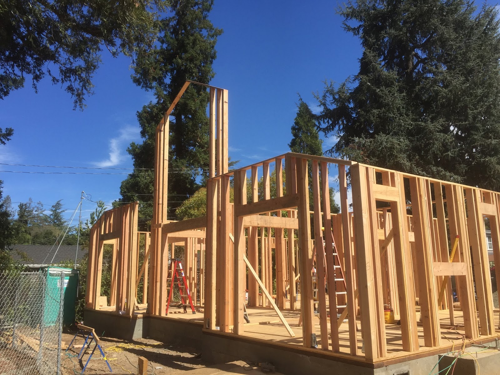
With 14 different floor levels in this 11,000 sqft house at Black Mountain, it's critical that the wall lines are perpendicular ,to make sure the walls are square to each other. The perimeter of the house turns 3 times at an 120° angle making it even harder to layout with the different floor levels. I used the equal length arc technique to snap perpendicular lines used for reference lines to ensure that the walls are perpendicular/ square.
After laying out the outside wall lines, I also laid out the Hip Rafters, Valley Rafters, Ridges and Cripple Hip Rafters in plan view. I needed to lay out the roof in plan view to locate all of the roof beam bearing points for 6x6 and 6x8 post. I also, laid out the profile/common rafter in plan view to check the geometry of the roof lines in plan view verse theoretical/mathematical dimensions. With the outside wall lines being perfectly square, most of the geometrical rafter lengths were perfect with the theoretical/mathematical dimensions. There was one profile/common rafter length in plan view on the sub-floor that was off by a 1/16" . I can make that work.


For the sloping ridge on this roof I drew it out in Google SketchUp. It's not that hard to draw in a CAD program, but laying it out in plan view on the sub-floor required a lot more work.


The first challenge to drawing out this area of the roof in plan view was to draw out the hip rafter runs in plan view. Two locate the hip rafters with the 45° and 60° plan view angles, I draw out two perpendicular lines from each eave line. The intersection of the perpendicular lines locate a point that the the hip rafter runs in plan view are drawn through. I could have used trigonometry , law of sines, to locate the intersection of the two hip rafter runs in plan view, but using the full scale geometry with perpendicular lines was a lot faster than trying to find the correct law of sines trigonometric formula and then running through all of the trigonometric calculations to find the profile/common rafter run for the equal pitched roof.

A line drawn through intersection of the extended eaves lines and through the intersection of the two hip rafters in plan view develops the sloping ridge in plan view.
When your drawing the geometry for the sloping ridge on paper or in a CAD software program you can extend the eaves lines easily. However, here I would have to extend the eave lines 30 feet off of the sub-floor. This is were I decided that using the Thales beam compass would be easier than trying to extend the eave lines 30 feet off the edge of the sub-floor.

Thales Beam Compass


When you extend the eave lines of a roof with a sloping ridge you can bisect the extended eave lines to find the angle of the sloping ridge in plan view. On this house there's a 60° angle off the eave line for one side of the roof. Using a 30°,60°,90° triangle you bisect the 30° at the intersection of the eave lines which leaves an angle of 15° for the sloping ridge in plan view.

The length of the Thales beam compass is 57.29578"(57 5/16"). After you draw an arc using the radius of 57 5/16" you measure along the arc, the length of the angle you want to draw. For the sloping ridge that's an angle of 15°, so I measured off an arc length of 15" and drew a line through the 15" mark on the arc to develop the sloping ridge in plan view.
I could have used trigonometry or a calculator to draw out a 15° triangle to establish the sloping ridge in plan view, but the Thales beam compass seemed like the correct tool to use after drawing out the hip rafter runs in plan view, by only using geometric lines.
The Thales beam compass concept was taught by Billy Dillon at the Ancient Knowledge Tour on Roof Framing. It didn't seem all that important at the time Billy explained this to the class, but sure enough anything Billy takes the time to explain seems to always make a complex task a lot easier.
Math for the Thales Beam Compass
Pi = 3.14159
Degrees to Radians = Pi ÷180 (3.14159 ÷ 180 = 0.017453)
Radians to Degrees = 180 ÷ Pi (180 ÷ 3.14159 = 57.295827)
Angle = 15° = 15 x 0.017453 = 0.261799
Arc Length = 57.29578 x 0.261799 = 14.9999" = 15"

First draw a line parallel with eave line, at the Intersection of the Hip Rafters in Plan View.
Use the Thales beam compass to draw an arc, then measure off 15" on the arc to draw the 15° angle for the sloping ridge in plan view. If the angle was 27.5° than we measure off an arc length of 27 1/2" . For a 90° angle you would measure off an arc length of 90", 180" for an angle of 180°. etc...

Now we need to check our drawing, to make sure the sloping ridge is drawn correctly in plan view for this equal pitched roof slope, before we can draw the vertical rise triangles to establish the slope angle of the sloping ridge in elevation.

Draw perpendicular lines from the eave lines at any point on the eaves lines. These two perpendicular lines intersect at the sloping ridge in plan view and must be the same length.
Next we can draw some profile rafter slope triangles to draw out the vertical rise triangle for the sloping ridge in elevation to determine the slope angle of the sloping ridge in elevation/profile.


After I snapped the lines on the sub-floor I sprayed clear lacquer over the chalk lines , so they'll still be there a month from now when I'm cutting the the roof rafters.