Friday, January 31, 2014

Claw Barbe Klaue Lip Angles

Different types of geometric development for Claw / Barbe / Klaue / Lip Angles.
Keywords

  1. Flächenschiftung
  2. Lotschiftung
  3. Klauenschiftung
  4. Kehlklauenschifter
  5. Gratklauenschifter 
  6. Shiftung
  7. Shiften
  8. Klaue
  9. Barbe
  10. Beard


German method of drawing out the claw for the jack rafter at the valley. Only works on equal pitched roofs.


French method of drawing out the purlin rafter claw. Works on unequal pitched roofs.


Another example of developing the claw angle on the purlin rafter.


The rafter claw is developed from the intersection of 3 planes.
  1. The plane on the bottom of the hip rafter.
  2. The plane on the bottom of the rafters.
  3. The Roof Surface Plane.
The intersection of the roof surface plane and the bottom of the hip rafter plane develop a line of intersection that is parallel to the hip rafter. The intersection of the plane on the bottom of the rafters and the plane on the bottom of the hip rafter develop a line of intersection that is parallel to the hip rafter.


The next 3 drawings are for the jack rafter claw on the Valley Rafter.


Two more methods of drawing out the jack rafter claw in profile.


Drawings showing the folding roof surface method for the rafter claw.


Draw down technique, flächenschiftung, for developing the claw angles on the roof surface.


Devers de pas Sloping Ridge Dormer

Sloping Ridge Dormer drawn out using dever de pas for the jack rafter perpendicular to the roof surface. After I developed the geometric drawing I realized I had done a great job developing the trigonometry for devers de pas for my Rafter Tools apps, but never developed the geometry to actually draw out the  rafter. Time to open up Louis Mazerolle's book, Traite Theorique Et Pratique De Charpente again.


Tuesday, January 28, 2014

Rotated Hip Rafters Without Backing Angle

Update: 2-28-14
This blog article is still valid, but see Tréteaux Roof Framing Kernel and Claw Lines  and the Tréteaux Angles Check for more information on Hip Rafters rotated into the roof surface.
_____________________________________________________________________________

Will Beemer, at the Heartwood Timber Framing school in Washington Massachusetts was going to post this at JLC in the Devers De Pas thread, but couldn't login to the JLC forum.

http://www.heartwoodschool.com/

Anyway, the reason that traditional European carpenters rotated the hip rafter was so that they didn't have to cut a backing angle, I assume. Doing this without power tools would be a burden. In modern work I think they mostly use plumb sided members, like us. But they still need to know the old way since so much of their work is restoration.

This peaked my interest in the rotated hip rafters, especially the rotated hip rafter with jack rafters that have a 90° miter angle. This is kinda like an oxymoron You have to know how to draw out the hip rafter backing triangle in plan view to rotated the hip rafter material, so you don't have to cut the backing angle on the hip rafters. It definitely wouldn't work in stick framing with 2x hip rafter material, but it would work in Timber Framing  with a square hip rafter, like a 12x12 hip rafter. 


3D perspective of the hip rafter rotated at the hip rafter backing angle.

With the hip rafter rotated at the hip rafter backing angle the miter angle on the side of the jack rafter is 90°, while the jack rafter back bevel angle, 39.76°, is the same for hip rafters that are plumb.


On the other side of the jack rafter the back bevel angle is the same, but what's interesting here is the claw angle. The claw angle is the same as the roof slope angle. In these drawings the profile roof slope pitch is an 8:12 pitch or an 33.69007° slope angle.


Here I've the hip rafter material, 10x10, rotated at the hip rafter backing angle. Then using the 1.3121 dimension as the hip rafter profile depth I can develop the footprint of the hip rafter in plan view.


Drawings showing the geometric development of the jack rafter miter angle, back bevel angle and the claw angle for the left side of the drawing.


Fairly easy development for the jack rafter miter angle and claw angle using the jack rafter profile development and the DP lines that defines the Upper Claw Angle.


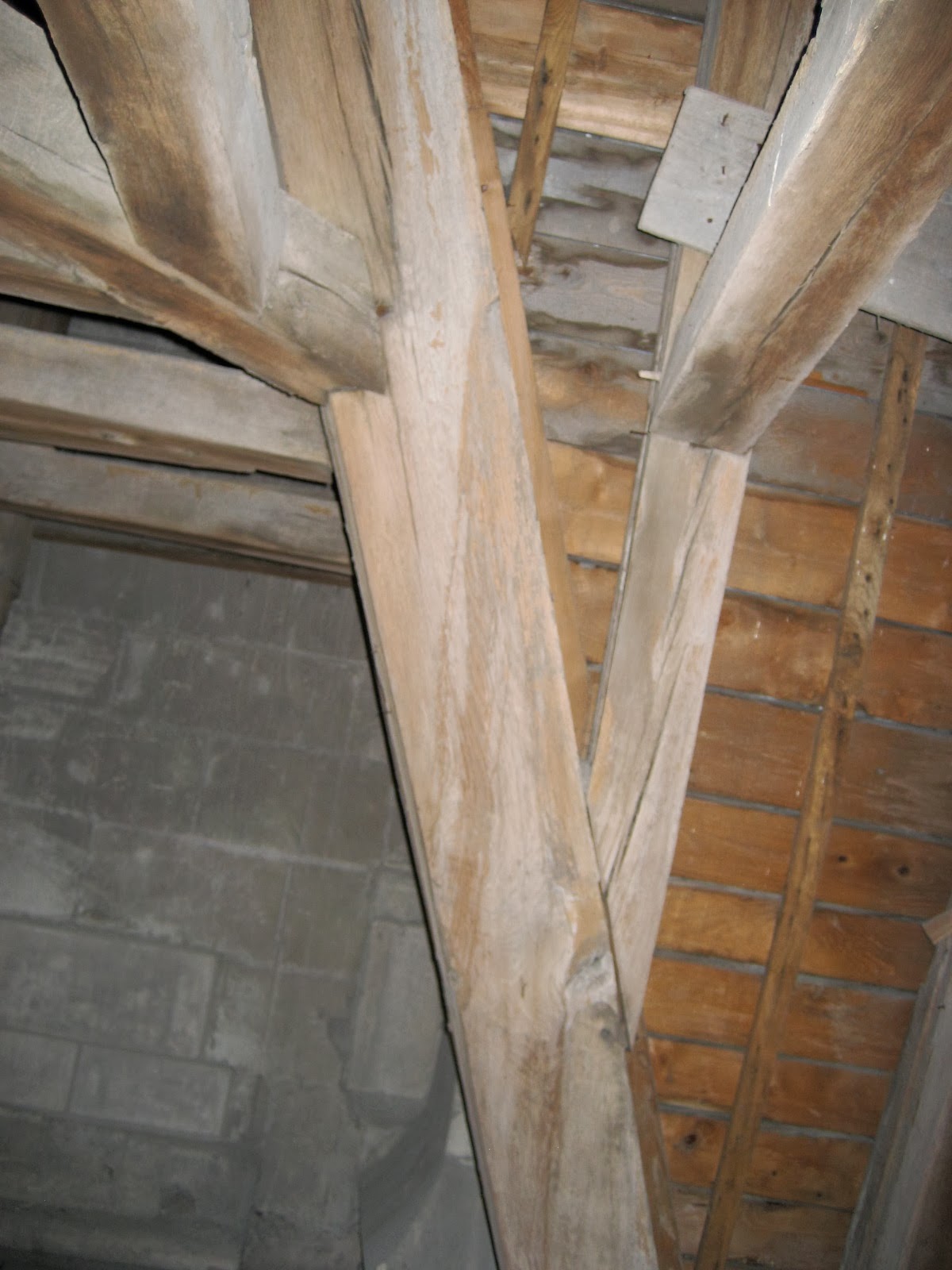
Pictures  that Billy sent me showing the hip rafter rotated. 


Here's a jack rafter with a 90° miter angle for the head cut at the hip rafter. This is from my study on the Tréteaux Dit Cadet task model. Where the sawhorse/hip rafter is rotated into the roof surface plane.


Hip rafter rotated in roof surface plane.


Hip rafter backing angle that defines the footprint of the hip rafter to place one edge of the hip rafter into the roof surface plane.


Sunday, January 19, 2014

2011 London Dormer #3

More theories on the sloping ridge dormers. The sloping ridge on the dormer is actually a hip rafter, so I developed the ground plan for the hip rafter and then used the standard folding roof surface development. With the folding roof surface it's easier to develop the lines for the jack rafter miter and bevel angles, as well as the claw lines.

Sloping Ridge Dormer Ground Plan
with the hip rafter plan angle, profile rafter slope angle and the hip rafter slope angle. Once you establish the hip rafter run line based on the slope of the sloping ridge you can draw the Eave Line / Ground Line / Gutter Line / Sewer Line / Égout / Hauptdachtraufe / Main Roof Eaves /Trauflinie / Eaves.


The profile rafter run is always perpendicular to the Eave Line.

You can use the rafter length of the profile rafter to establish the real roof surface of the dormer.


In this drawing I'm checking the geometric roof surface development on the real roof surface of the sloping ridge dormer.


Perspective view of the sloping ridge dormer developed as a hip rafter.


Here we have the hip rafter in elevation. The profile rafter drawn with the depth of the jack rafter perpendicular to the roof and the hip rafter development on the roof surface for:
  1. Line of the Base of Hip Rafter
  2. Line of the Face of the Hip Rafter
  3. Internal Edge of Hip Rafter on Roof Surface
  4. Claw Line at the Top of the Hip Rafter Claw Plane
  5. Claw Line for the Bottom of the Hip Rafter Claw Plane 


I used the hip rafter backing triangle with the rafter profile block rotated for the dimension of the Internal Edge of Hip Rafter on Roof Surface.


Finally I developed the jack rafter perpendicular to the roof surface by placing the timber over the drawing on the roof surface for the miter line on the side of the jack rafter, back bevel angle on the top & bottom of the jack rafter and the claw lines.


I still need to work on the miter, back bevel and claw lines at the foot of the jack rafter.

The main problem with using the roof surface for the development is size. This technique would never fit on an 8' x 8' drawing board.


I did check the jack rafter perpendicular to the roof surface with my Rafter Bevel Angles app for Android and my geometric drawing was correct except for the claw angle. The drawing had a claw angle of 30.4° while the Rafter Bevel Angles app had a claw angle of 28.33130°. Not sure what that's all about.

Rafter Tools -- Jack Rafter Plumb To Earth Offset Bevel Angles
Profile Rafter Slope Angle
37.87752°
Hip Rafter Plan Angle
10.69718°
Hip Rafter Slope Angle
8.21576°
Hip Rafter Edge Bevel Backing Angle
37.10703°
Jack Rafter Offset Angle
30.53374°
Jack Rafter Foot
Miter Angle Side
36.76964°
Bevel Angle Top Edge
24.96761°
Jack Rafter Peak
Miter Angle Side
45.45514°
Bevel Angle Top Edge
129.77149°
Jack Rafter Claw Angle At Hip Rafter
28.33130°
Tail Slope Angle
90.00000°
Rafter Witch Cut Miter Angle
90.00000°


Monday, January 13, 2014

2011 London Dormer #2

Still haven't developed the jack rafter perpendicular to the roof surface, but these drawings are a start in the right direction. They develop the sloping dormer profile slope angle.

Keywords to search with in German
Schifter und Wechsel, im rechten Winkel zur Dachfläche.
gauben profil kehlbohenschifter

Ground Plan for the Kehlbohenschifter (Valley Jack Rafter)

Ground Plan, Elevation and GaubenProfil (Dormer Profile) for the Kehlbohenschifter


 Another way of developing the sloping ridge dormer profile slope angle.

The sloping ridge is technically a hip rafter, so we can develop the dihedral angle triangle, the angle between the two planes. This gives us the sloping ridge backing angle.