Friday, October 31, 2014

Carpentry & Building 1890


Some interesting and funny comments from the magazine Carpentry & Building  published in 1890.


Fig. 5 shows  this  method  of  getting  the hip rafter backing on  both  sides  of  an  irregular  hip
rafter.   It has been already explained, by getting the distance in plan. This letter would have been unnecessary and not deprived me of my afternoon nap, if the reader would have followed the laws of geometry.

Fig 5 Irregular Hip Roof

Fig 6 Equal Pitched Hip Roof

This is funny. The drawing is correct and is the most simple to follow and the best for general use to determine the hip rafter backing angles.
______________________________________________________________
Which Rule for Backing Hip Rafters is the Best?
From HAH Avoca Wis

 Will you please inform me which of the various rules you have published for backing hip rafters you consider the most simple to follow and the best for general use.  I have examined the correspondence containing these rules and find that one writer pronounces this one Pitch of Hip Batter Backing Hip Rafters Fig 2 Sketch Accompanying Letter from CO incorrect and another brands that one as shaky &c and I am really doubtful which one to follow Will you have the kindness to set me on the right track.


Sunday, October 26, 2014

Layover Valley Rafter Hexenschnitt #2

English translation for Witches Cut


In the book
Das neue Buch vom alten Wissen der Schiftung
The new book on the ancient knowledge Schiftung
The new book on the ancient knowledge Roof Framing
The new book on the ancient knowledge Roof Framing Geometry
by Bernd Küppers


Does this make sense?
______________________________________________
Witches cut: Hexenschnitt:

Example 3: The true witches cut using the basic method

On unequal pitched roofs the hip- or valley rafter is inclined less than the rafters or jack rafters and it gets the so-called witches cut eave cut (tail cut). This witches cut only occurs on tail cuts that are not plumb cuts at the eave line. If the unequal sloped main and adjacent roof rafters have a right angle rafter tail cut (square tail fascia) and this cut direction is transmitted to the hip rafters, one speaks of a true witches cut.

To illustrate a cross-sectional direction it requires two points at different heights. The eave line as height 0 (zero) offers itself as the first point in elevation.

The second elevation line, in the example image -30 cm, you can choose at will. The farther they are away from each other, the more accurate the scribing. It is important that the same elevation line height is chosen in all profiles.

If you now extend the direction of the tail cut, down to the elevation line, there are two points of intersection.

Firstly, the cutting direction with eave height and on the other one is the cutting direction with elevation line -30 cm.

Drop plumb lines from these intersections at the elevation line and run them through to the ground plan, until they meet the edge of the hip rafter ground plan.

The newly acquired points you plumb back to the hip rafter profile in elevation, its height accordingly, and connecting the point with the one at the hip rafter elevation line.

If you connect the intersection of the elevation lines and the intersection of the eaves, there is the resultant edge of the witch’s cuts in the ground plan.

If you bring the two points, of its height according, to the hip rafter profile, you get the actual view of the completed work at the hip rafter tail cut.


___________________________________________________

Note: I used 150mm in my example drawings for the elevation line.


Saturday, October 25, 2014

Layover Valley Rafter Hexenschnitt #1

While studying the: The Layover Valley Sleeper with Witch Cut
Die Kehlbohle mit Hexenschnitt

In the book
Das neue Buch vom alten Wissen der Schiftung
The new book on the ancient knowledge Schiftung
The new book on the ancient knowledge Roof Framing
The new book on the ancient knowledge Roof Framing Geometry
by Bernd Küppers

I realized I need to backtrack and draw out the roof surface averaging lines used to determine the ground plan roof framing geometry, the intersection of lines of the individual roof surfaces. I could have cheated and used my RafterTools Calculator app for the plan angles of the three different roof slopes on the task model, but then it would have defeated the purpose of studying the Shiftung geometric method for the witches cut of the layover valley sleeper. Just a refresher in developing the plan angles using geometry only.

Dachausmittlung
Roof Design
from
Intersecting Roof Surfaces


Optional Roof Design:
Here's the roof surface design for the PIA equal overhang. 


Here's the plate heights for the PIA equal overhang.


Thursday, October 23, 2014

Einführung ins Flächenklappung

We need an German to English translation for the folding roof surface.

From Bernd Kuppers book:
German
Erweiterung
Einführung ins Flächenklappung

English
Extension
Introduction to Surface Folding


Plane Joinery?
Maybe the "Joinery Plane"?

Yes, it's the plane where you develop the geometrical lines for the rafter joinery.

Roof Surface Plane
Dachfläche
Dach = Roof
fläche = Surface
Ebene = Plane ???

flächenklappung
flächen = Surface
klappung = Folding


Sunday, October 19, 2014

Fledermausgaube mit gerader Kehle

In the book
Das neue Buch vom alten Wissen der Schiftung
The new book on the ancient knowledge Schiftung
The new book on the ancient knowledge Roof Framing
The new book on the ancient knowledge Roof Framing Geometry
by Bernd Küppers


on page 94 , he describes the geometric technique to draw out an eyebrow dormer that rest on two canted valley rafters. I'm posting this drawing hoping that Bernd will comment on the questions I have on this drawing technique.


Bernd's answer

hello Sim
the angle between the hip line and the auxiliary line in the arc, is not necessarily 90 °. The important thing is, that the pitch break holds at least 3 tiles.
the legs of the upper triangle are hip lines and form the transition between curved and straight roof surface.
the third is the valley line in the front view
and the fourth is indeed the inner top edge of the inner valley rafter.

Bernd's suggestion
If you want, you can add the pages of the eyebrow dormer to your blog. This should explain the drawing method of the straight valley line.
I'm helping Bernd translate his book to readable English. Billy or Brad take a look at Bernd's current English translation and see if it make sense.  I think the biggest difference between his method and what I know on eyebrow dormer roof design, is the concept of designing the eyebrow dormer for tiles, instead of composition shingles.


Here's an image of the eyebrow dormer with the straight throat that Bernd Kuppers shared.


Here's a drawing by Bernd Brueck showing the hip and valley rafter of the eyebrow dormer and ribs with a straight throat.
Here's a link to the 3-D PDF file
Bernd Brueck Fledermausgaube


Saturday, October 18, 2014

Tilted Valley Rafters


Das neue Buch vom alten Wissen der Schiftung
The new book on the ancient knowledge Schiftung
The new book on the ancient knowledge Compound Joinery
The new book on the ancient knowledge Roof Framing
The new book on the ancient knowledge Roof Framing Geometry
by Bernd Küppers

More images and information on the book can be found at this link.
Image from Bernd's Facebook page on Shiftung.


Verkanteter Kehlsparren in German = Tilted-Canted- Rotated Valley Rafter

Looking at page 52 in his book I decided it was time to study the valley rafters rotated into the roof surface plane. The same geometric techniques used for hip rafters rotated into the roof surface plane   can also be used for the valley rafters rotated into the roof surface plane.  Some of the geometry used for valley rafters rotated into the roof surface plane is empirical-type knowledge. Information gained by means of observation, experience, or experiment. From this empirical knowledge we know the valley jack rafters miter head cut will be 90° and the bevel cut, top cut, will be the same as the jack rafter bevel angle for plumb hip-valley rafters.

We also have a language problem when we're studying Verkanteter Kehlsparren or Verkanteter Gratsparren . What do we call each side of the canted  hip or valley rafter rotated into the roof surface plane. 

Looking Michel Verdon's post on 
Principes du dévers: la sauterelle
or
Principles of cant: the grasshopper

he labels each side of the rotated hip rafter in plan view as A for the side of the roof the hip rafter is rotated into and the canted side as the DP side of the hip rafter.

DP = Dévers De Pas .... need a German name for this side of the canted hip rafter.
TC = Trait Carré = Perpendicular .... need a German name-word -- senkrecht ?

 I purpose labeling all canted hip or valley rafters in plan view as TC, for the side the hip-valley rafter is rotated into, and DP as the side of the hip-valley rafter that's canted-Tilted from plumb.

Example for the TC side of  the hip-valley rafter is rotated into the roof surface plane:

Plumb hip-valley rafter
Jack Rafter Miter Angle = 33.69° = Roof Slope Angle
Jack Rafter Bevel Angle = 39.76°

Rotated hip-valley rafter
Jack Rafter Miter Angle = 90.00°
Jack Rafter Bevel Angle = 39.76°

For equal pitched roofs for the canted-DP side of the hip-valley rafter:

Plumb hip rafter
Jack Rafter Miter Angle = 33.69° = Roof Slope Angle
Jack Rafter Bevel Angle = 39.76°

Rotated hip rafter
Jack Rafter Lower Claw Angle = Roof Slope Angle
Jack Rafter Bevel Angle = 39.76°

So the only angle we need to draw out or calculate for the jack rafters for the rotated hip rafter  is the Jack Rafter Upper Claw Angle on the DP side of the hip rafter.

Since the canted-tilted valley rafter is just an upside down hip rafter the only angle we need to calculate is the Jack Rafter Upper Lower Angle on the DP side of the valley rafter.


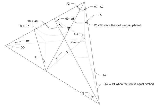
Drawing from one of my studies on the hip rafter rotated into the roof surface plain using more of the French technique "l'art du Trait" rather than the German Shiftung technique. Some times the German Shiftung roof framing geometry technique for developing the geometry of a compound joint just has too many development lines.  Here in this drawing, you can use my Axiom #3 for the line that develops the Upper Claw Angle on the jack rafter on the DP side of the hip rafter. It would develop the jack rafter Lower Claw Angle for the DP side of the valley rafter.

Roof Framing Geometry Proposition – Axioms # 3:
The intersection of the DP Lines of two rafters define the line for the upper claw angle on the rafter.


 In this drawing of the rotated hip rafter the Upper Claw Angle for the jack rafter on the DP side of the hip rafter is 12.11976°.
  In this drawing of the rotated hip rafter the Upper Claw - Miter  Angle for the jack rafter on the TC side of the hip rafter is 90.00°.


 In this drawing of the rotated valley rafter the Upper Claw Angle for the jack rafter on the DP side of the hip rafter is 52.00°, same as the roof slope angle, and the Lower Claw Angle is 12.11976°.


The Lower Claw Angle is 12.11976° for the jack rafter on the DP side of the rotated valley rafter.
Same as the Upper Claw angle for the jack rafter on the DP side of the rotated hip rafter.


You can also use my tréteaux roof framing calculator to verify these angles.
Trèteaux Angles: P16a-DP
P16a-DP = Adjacent Side Jack Rafter Miter Angle on DP Side Of Hip Rafter on Face Perpendicular To Roof Surface, Lower Claw Angle ... this would be the Upper Claw angle for the jack rafter on the DP side of the rotated valley rafter.


Trèteaux Angles: P17a-DP
P17a-DP = Adjacent Side Jack Rafter Miter Angle on DP Side Of Hip Rafter on Face Perpendicular To Roof Surface, Upper Claw Angle... this would be the Lower Claw angle for the jack rafter on the DP side of the rotated valley rafter.

Trèteaux Angles: P18a-DP 
P18a-DP = Adjacent Side Jack Rafter Bevel Angle on DP Side Of Hip Rafter on Face Set in Roof Surface
This would be the back bevel, top cut, for the jack rafter on the DP side of the rotated valley rafter.

Tuesday, October 14, 2014

Obholz

Bernd Brück  sent me a couple more drawings. These represent the Obhölzer, rafter seat calculations.

Lotrechtes Obholz = HAP = Height Above Plate

Rechtwinkliges Obholz = What we would call the structural engineering D4 calculation. 

Sparrenhöhe = depth of rafter

Lotrechte Kerventiefe = Height Below Plate

Lotrechte Sparrenhöhe = Rafter Plumb Height

Dachneigung =  Rafter slope Angle

The standard American rafter seat calculations starts with the length of the seat cut or HAP of the rafter. The Germans and Europeans use the Rechtwinkliges Obholz   method. A dimension parallel to the top of the rafter.


Monday, October 13, 2014

German Roof Framing Translations to English

Dachneigung (Grad): = Roof Slope Angle
Gratsparrenneigung (Grad)= Hip Rafter Slope Angle (R1)
Gebäudegrundwinkel innen (Grad): = Eave Angle
Gratsparrengrundwinkel (Grad)=  Plan Angle
Abgratungswinkel (Grad)= Hip Rafter Backing Angle
Anreißwinkel (Grad)= Hip Rafter Side Cut Angle
Schifter Anreißwinkel (Grad)= Jack Rafter Side Cut Angle
Hexenschnitt (Grad)= Witches Cut = ( 90° - R2)
Backenschmiege = Back Bevel
Dachausmittlung = Roof Design
Hauptdach = Main Roof = HD
Kerve = Birds Mouth = Seat Cut
Pfetten = Purlin
Traufe = Eave
Stirnbrett = Fascia
Traufabschnittswinkel (Grad)=  For Hip Rafter Angle Q3 = Projected Fascia Pitch Angle + Hip Pitch Angle
or
90° - (R1+R2) = 90° - ( Hip Rafter Slope Angle + Hip Rafter Purlin Housing Angle)


Hip Rafter Miter Angle = 90° - (Projected Fascia Pitch Angle + Hip Pitch Angle)
Hip Rafter Miter Angle = 90° - (46.69° + 25.24°) = 18.07°
Verstichmass = Hip Rafter Plumb Line Shift dimension

Abgratung = hip rafter backing
Auskehlung = valley rafter backing

Bernd Brück a Zimmerie from Germany sent this drawing for the translation.


Dachneigung (Grad): = Roof Slope Angle
Traufabschnittswinkel (Grad): This angle is only used for the hip rafter. It would be angle 90 - Q3.


Sunday, October 12, 2014

Hip Rafter Plumb Line Shift

Math for equal pitched roofs for Hip Rafter Plumb Line Shift 
(1/2 of hip rafter width) * tan( 90° - plan angle) = Hip Rafter Plumb Line Shift  dimension
(0.75) * tan( 90° - 45) = 0.75


Hip Rafter Shift Dimension in Decimal Inches 


Hip Rafter Width1.51.752.533.1253.55.1255.5
Rectangle - 90°0.750.8751.251.51.56251.752.56252.75
Pentagon - 108°0.544910.635720.908181.089811.135221.271451.861771.99799
Hexagon - 120°0.433010.505180.721690.866030.902111.010361.479461.58771
Octagon - 135°0.310660.362440.517770.621320.647210.724871.061421.13909

Hip Rafter Shift Dimension in Fractions of Inches

Hip Rafter Width1 1/21 3/42 1/23 3 1/83 1/25 1/85 1/2
Rectangle - 90°3/47/81 1/41 1/21 9/161 3/42 9/162 3/4
Pentagon - 108°9/165/815/161 1/161 1/81 1/41 7/82
Hexagon - 120°7/161/23/47/87/81 1 1/21 9/16
Octagon - 135°5/163/81/25/85/83/41 1/161 1/8

Hip Rafter Shift Dimension in Millimeters (mm)


Hip Rafter Width40608090100110120130
Rectangle - 90°2030404550556065
Pentagon - 108°14.5308521.7962829.0617032.6944136.3271339.9598443.5925547.22526
Hexagon - 120°11.5470117.3205123.0940125.9807628.8675131.7542634.6410237.52777
Octagon - 135°8.2842712.4264116.5685418.6396120.7106822.7817524.8528126.92388

Hip Rafter Edge Bevel and Backing Angle

In complex roof framing there are 7 main roof framing angles.

  1. Hip Rafter Backing Angle
  2. Valley Sleeper Bevel Angle
  3. Plain Titl (DP)
  4. Main Plan Angle
  5. Adjacent Plan Angle 
  6. Main Profile Rafter Slope Angle
  7. Adjacent Profile Rafter Slope Angle
In this article I will discuss the hip rafter backing angle and the valley sleeper bevel angle. These two angles determine the miter angle and and saw blade bevel angles for jack rafters and purlin rafters that are plumb to the earth and for jack rafters and purlin rafters that are skewed from the eave line. A thorough knowledge of these two angles is critical in complex roof framing using geometry or trigonometry.

The hip rafter edge bevel was avoided in the 12th century on some roof structures by rotating the hip rafter into the roof surface plane. However, by avoiding the hip rafter edge bevel, the carpenters-builders had to have a knowledge of the Valley Sleeper Bevel Angle. They didn't call it the Valley Sleeper Bevel Angle, but it's the same angle we use today for valley sleepers, layover valleys or hip rafters rotated into the roof surface.

The hip rafter edge bevel (Hip Rafter Backing Angle) is determined by the dihedral angle triangle. The dihedral angle is formed by the intersection of two adjacent planes. In hip roof framing the dihedral angle is formed by the intersection of the roof surface planes at the hip or valley rafter. The square edge of the hip rafter at this intersection must be edge beveled to align the edge of the hip or valley rafter with the adjoining roof surface plane. The hip rafter could also be lowered to align the edge of the hip with the adjoining roof surface plane ( hip drop).

There are several ways of geometrically drawing out the hip rafter geometry for determining the hip rafter edge bevel. Each geometric method will give the correct hip rafter backing angle. However, some methods are not that accurate for use with an bevel gauge or transferring the hip rafter edge bevel from the geometric lines of a drawing unless the drawing is a full scale geometric drawing of the roof.

Drawing showing the dihedral angle formed by two intersecting planes.


3D drawings of the roof framing kernels showing the different ways of drawing out the dihedral angle for the hip rafter edge bevel angle.


Geometric drawings of simple folded out roof framing kernels showing the different ways of drawing out the dihedral angle for the hip rafter edge bevel angle.


In this drawing of an irregular hip roof, folded out roof framing kernel. the hip rafter backing triangle is drawn perpendicular to the hip rafter run line at the peak of the roof framing kernel. This is the most accurate way to draw out the hip rafter backing angles. You can also use this same roof framing kernel for drawing the hip rafter rotated into the roof surface to determine the Valley Sleeper Bevel Angle.


Warning
This method of drawing out the hip rafter backing angle
only works on equal pitched roofs with a 90° eave angle.

However, this geometric method should be common knowledge for use in the field for simple hip roof framing.


Here's a classic drawing showing the hip rafter backing angles developed geometrically. This classic drawing of the hip rafter backing angles was more of an exercise in roof framing geometry for architects and road scholars of the 18th & 19th century. This drawing method only works when drawn full scale.


Most carpenters in the centuries pass would have drawn out the hip rafter in profile using the hip rafter shift geometry to determine the intersection of the Hip Rafter Shift Line & Level Line that determines the Hip Rafter Backing Depth Line. They didn't need the actual hip rafter backing angle. They would mark out the hip rafter backing depth lines on the sides of the  hip rafter and hand hew the hip rafter edge bevel.


There are three methods of backing out the hip rafter.
  1. Standard Equal Pitch Roof, with Hip Rafter Material Centered on Hip Rafter Run Line with Equal Hip Rafter Backing Depths
  2. Unequal Pitched Roofs, with Hip Rafter Material Centered on Hip Rafter run Line with Unequal Hip Rafter Backing Depths.
  3. Unequal Pitched Roofs, with Hip Rafter Material Shifted on Hip Rafter Run Line for Equal Hip Rafter Backing Depths.


Standard Equal Pitch Roof, with Hip Rafter Material Centered on Hip Rafter Run Line with Equal Hip Rafter Backing Depths Examples.

Rectangular  Roof Framing
Equal Pitch Roof,
with Hip Rafter Material Centered on Hip Rafter Run Line
with Equal Hip Rafter Backing Depths


Pentagon Roof Framing
Equal Pitch Roof,
with Hip Rafter Material Centered on Hip Rafter Run Line
with Equal Hip Rafter Backing Depths


Hexagon Roof Framing
Equal Pitch Roof,
with Hip Rafter Material Centered on Hip Rafter Run Line
with Equal Hip Rafter Backing Depths


Octagon Roof Framing
Equal Pitch Roof,
with Hip Rafter Material Centered on Hip Rafter Run Line
with Equal Hip Rafter Backing Depths


For most modern irregular hip roof framing you will use the hip rafter shift geometry for equal height heel heights on each side of the hip rafter that's the same as the HAP of the common rafters. However, there can be situations where the hip rafter material is centered on the corner of the plate line for timber framing joints on irregular hip roofs or where  the fascia lines of an irregular hip roof make it more desirable to keep the hip rafter material centered on the corner of the fascia.

Drawing with unequal pitched roof with the hip rafter material centered on the corner of the eave line. This results in different backing depths on each side of the hip rafter. This would also require different height plate lines or different heights for the common rafter HAP. (HAP = Height Above Plate)

Unequal Pitched Roofs, with Hip Rafter Material Centered on Hip Rafter run Line with Unequal Hip Rafter Backing Depths Example.


Unequal Pitched Roof, with Hip Rafter Material Shifted on Hip Rafter Run Line for Equal Hip Rafter Backing Depths Example


Hip Rafter Shift Geometry