Monday, March 31, 2014

Golden Rhombus Parallelogram Roof #5

Joes' drawings and notes of splitting the roof surface of the Golden Rhombus Parallelogram Roof. This method is similar to the Rhombicosidodecahedron Hip Rafters blog where the roof is cut into roof surface pieces, triangles, squares, pentagons, with the miter line of the roof  being  the sum of the jack rafter side cut angles at the peak  divided by 2. The hip rafters will be different widths, but for the parallelogram the hip rafters are centered on the hip rafter run line. This method also results in the width of the hip rafter backing length on the roof surface of the hip rafters being equal.

Here's a drawing showing this method. There's a difference in the width of the hip rafters, but it's not much of a difference.


There's 3 ways of mitering hip rafters and this method can be used on polyhedron's as well, where the plan angles are not equal, like the Rhombicosidodecahedron.

3 different ways of cutting the hip rafters head cuts on any roof surface.
  1. The normal way using R4P, hip rafter side cut angle at peak of hip rafter, but the hip rafter miter cuts will be different lengths for plan angles that are not equal.
  2. Using the hip rafter miter line in plan view, like my online script, or using traditional layout geometry.
  3. Bisecting the roof surface, like Joe's drawings. 

18° Hip Entries:
Plan Angle at Peak = 40°
μ = arctan (cos 18° tan 40°) = 38.5909583° (R4P)
β = 72° (90° – R1)
α = 26.56505° (C5)
Returns (rounded off):
MIT =  38.30262° (Angle on Roof Surface)
BEV = 59.59404° (90°– Section Plane Angle)
ρ = 16.42889° (Section Plane Angle – R5P)
Projected Right Angle =  103.97707° (90° + R5P)
Supplementary Angle =  76.02293° (90° – R5P)
Blade Angle along MIT Line = 9.49278° (Section Plane Backing Angle)
Blade Angle along β Line = 50.00000° (90° – DD ... Blade Bevel along 90° – R1)
Blade Angle along μ Line = 11.45699° (A5P ... Blade Bevel along R4P)

27.7323° Hip Entries:
Plan Angle at Peak = 50°
μ = arctan (cos 27.7323° tan 50°) = 46.52926239° (R4P)
β = 62.2677° (90° – R1)
α = 16.04506° (C5)


Returns (rounded off):
MIT =  43.42969° (Angle on Roof Surface)
BEV = 59.59404° (90°– Section Plane Angle)
ρ = 11.73413° (Section Plane Angle – R5P)
Projected Right Angle =  108.67183° (90° + R5P)
Supplementary Angle = 71.32817° (90° – R5P)
Blade Angle along MIT Line =  9.49278° (Section Plane Backing Angle)
Blade Angle along β Line = 40.00000° (90° – DD ... Blade Bevel along 90° – R1)
Blade Angle along μ Line = 20.88368° (A5P ... Blade Bevel along R4P)


  1.   


Rhombicosidodecahedron Hip Rafters

Rhombicosidodecahedron

From Wikipedia, the free encyclopedia
In geometry, the rhombicosidodecahedron, or small rhombicosidodecahedron,
is an Archimedean solid, one of thirteen convex isogonal nonprismatic solids constructed of two or more types of regular polygon faces.

Rhombicosidodecahedron


Archimedean solid

From Wikipedia, the free encyclopedia
In geometry, an Archimedean solid is a highly symmetric, semi-regular
convex polyhedron composed of two or more types of regular polygons meeting
in identical vertices. They are distinct from the Platonic solids,
which are composed of only one type of polygon meeting in identical vertices,
and from the Johnson solids, whose regular polygonal faces do not meet in identical vertices.


Rhombicosidodecahedron Vertex - Deck -- Ground Plan.


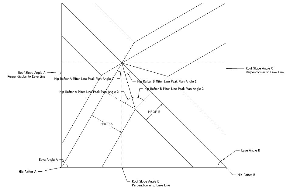
Rhombicosidodecahedron Roof Slope Angles with hip rafter offset for roof plane alignment.

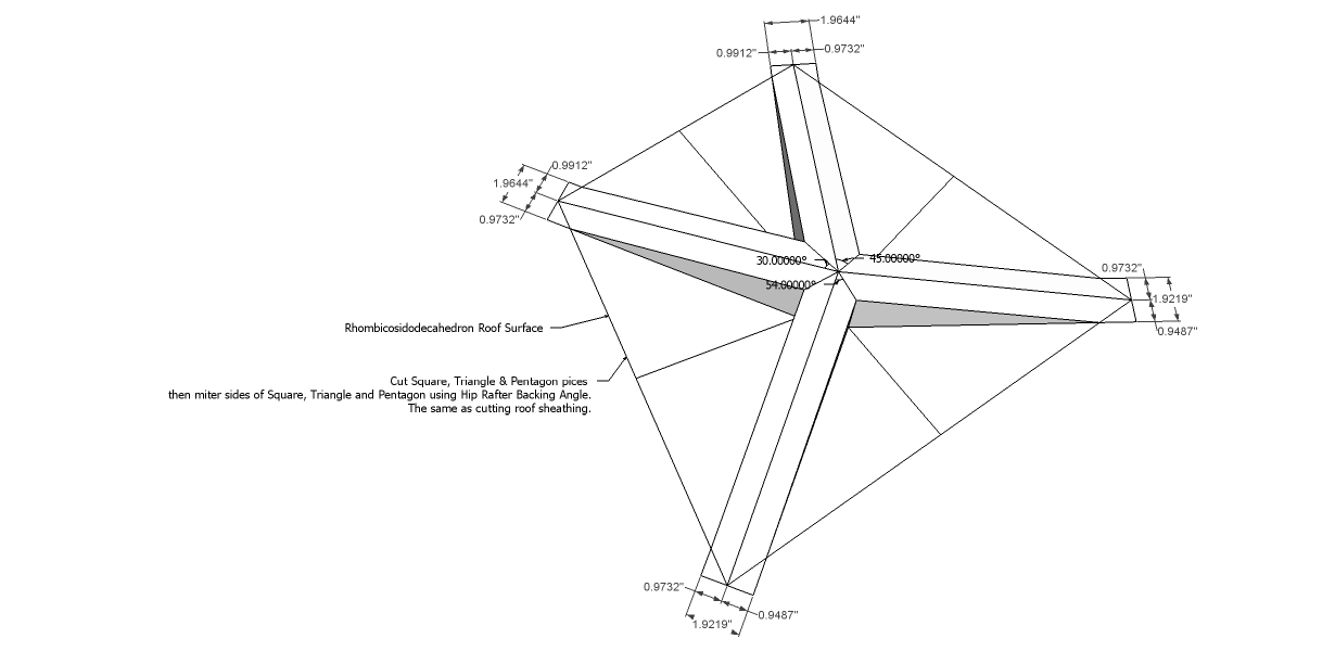
Rhombicosidodecahedron Roof Surface Unfolded.


Rhombicosidodecahedron Roof Surface Angles.
Cut Square, Triangle & Pentagon pieces, 
then miter sides of Square, Triangle and Pentagon using Hip Rafter Backing Angle.
The same as cutting roof sheathing. The hip rafters will be different sizes and the hip rafters will not be centered on the hip rafter run line.

Rhombicosidodecahedron Roof  Sheathing with a SkillSaw
  1. Cut 2 half square triangles with two legs at 12", the length of the hip rafter and a base leg of 16.97".  45° roof sheathing angles and 45° jack rafter side cut angles on the roof surface. Hip Rafter Backing Angle = Saw Blade bevel Angle = 18.46°
  2. Cut 1 equilateral triangle with edge lengths of 12". 60° roof sheathing angles and 30° jack rafter side cut angles on the roof surface. Hip Rafter Backing Angle = Saw Blade bevel Angle = 14.98°
  3. Cut 1 triangle for the pentagon side piece. Two legs at 12" and a base leg of 19 7/16". 36° roof sheathing angles and 54° jack rafter side cut angles on the roof surface. Hip Rafter Backing Angle = Saw Blade bevel Angle = 22.39° 


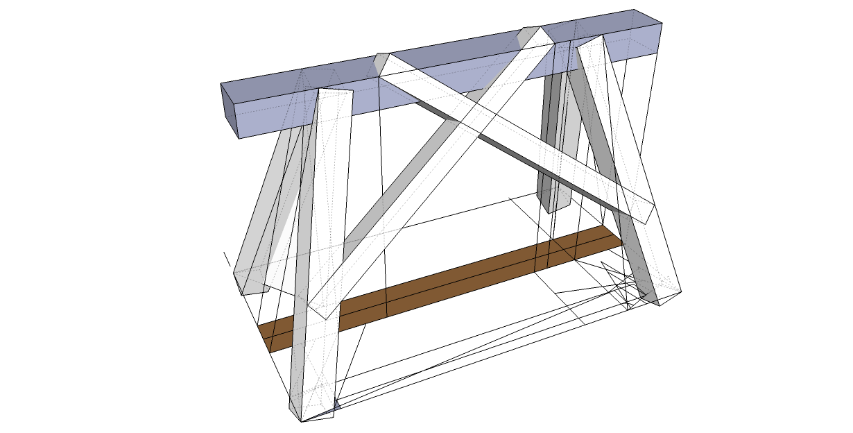
Rhombicosidodecahedron Hip Rafters with equal length miter line plane.
Hip Rafter Miter Angles
Hip Rafter Width = 1.00000

Roof Eave Angle for Hip Rafter A = 102.62142
Hip Rafter A Slope Angle = 12.93932
Roof Slope Angle A = 14.98460
Roof Slope Angle B = 18.46161
Plan Angle on Side A = 59.13432
Plan Angle on Side B = 43.48710

Roof Eave Angle for Hip Rafter B = 77.37858
Hip Rafter B Slope Angle = 12.93932
Roof Slope Angle B = 18.46161
Roof Slope Angle C = 22.39277
Plan Angle on Side B = 43.48708
Plan Angle on Side C = 33.89150

Plan Miter Peak Angle = 93.02582
Hip Rafter A Offset Perpendicular = 0.36180
Hip Rafter B Offset Perpendicular = 0.58541

Hip Rafter A Miter Line Peak Plan Angle 1 = 32.53731
Hip Rafter A Miter Line Peak Plan Angle 2 = 57.46269

Hip Rafter B Miter Line Peak Plan Angle 1 = 60.48851
Hip Rafter B Miter Line Peak Plan Angle 2 = 29.51149

Hip Rafter A Miter Line Slope Angle R5P = 10.96195

Hip Rafter B Miter Line Slope Angle R5P = 6.45702

Hip Rafter A R5B = 9.46376

Hip Rafter A R5B = 9.46376

Hip Rafter A - R4P Angle = 31.87278

Hip Rafter B - R4P Angle = 59.85263

Hip Rafter A
Compound Miter Angle and Saw Blade Bevel Angle
Settings for Cutting Material Laying Flat-- Side Face
Hip Rafter A Miter Angle = 12.93932
Hip Rafter A Saw Blade Bevel Angle = 57.46269

Hip Rafter B
Compound Miter Angle and Saw Blade Bevel Angle
Settings for Cutting Material Laying Flat-- Side Face
Hip Rafter B Miter Angle = 12.93932
Hip Rafter B Saw Blade Bevel Angle = 29.51149

Hip Rafter A
Compound Miter Angle and Saw Blade Bevel Angle
Settings for Cutting Material On Top Edge

Hip Rafter A Tetrahedron Angles
D Angle = 77.06068
A Angle = 32.53731
C Angle = 31.87278
E Angle = 10.96195
B Angle = 6.91718
90-D Angle = 12.93932
90-A Angle = 57.46269
90-C Angle = 58.12722
90-E Angle = 79.03805
90-B Angle = 83.08282

Saw Miter Angle = 58.12722
Saw Blade Bevel Angle = 6.91718
Bevel Angle (Compound Angle) = 12.93932

Hip Rafter B
Compound Miter Angle and Saw Blade Bevel Angle
Settings for Cutting Material On Top Edge

Hip Rafter B Tetrahedron Angles
D Angle = 77.06068
A Angle = 60.48851
C Angle = 59.85263
E Angle = 6.45702
B Angle = 11.23695
90-D Angle = 12.93932
90-A Angle = 29.51149
90-C Angle = 30.14737
90-E Angle = 83.54298
90-B Angle = 78.76305

Saw Miter Angle = 30.14737
Saw Blade Bevel Angle = 11.23695
Bevel Angle (Compound Angle) = 12.93932


Rhombicosidodecahedron Dihedral Angles and Hip Rafter Backing Angles


Angular Dimension (159.09484°)
Dihedral Angle = 159.094842552°
30° - 7.6226318595° ... Hip Rafter Backing Angle
45° - 13.2825255889°... Hip Rafter Backing Angle

Face Angle A = 45.00000 ... Roof Sheathing Angle
Face Angle B = 60.00000 ... Roof Sheathing Angle
Face Angle C = 102.62142 ... Eave Angle

Dihedral Angle A = 14.98459 ...Common/Profile Rafter Slope Angle
Dihedral Angle B = 18.46160...Common/Profile Rafter Slope Angle
Dihedral Angle C = 159.09486


Angular Dimension (148.28252°)
Dihedral Angle = 148.282525587°
45° - 13.2825255889°... Hip Rafter Backing Angle
54° - 18.4349488239°... Hip Rafter Backing Angle

Face Angle A = 45.00000...Roof Sheathing Angle
Face Angle B = 36.00000... Roof Sheathing Angle
Face Angle C = 77.37858... Eave Angle

Dihedral Angle A = 22.39278...Common/Profile Rafter Slope Angle
Dihedral Angle B = 18.46162...Common/Profile Rafter Slope Angle
Dihedral Angle C = 148.28251

Dihedral Angle Formulas
Dihedral angle C = arccos((cos(c) - cos(a) × cos(b)) ÷ (sin(a) × sin(b)))
Dihedral angle A = arccos((cos(a) - cos(b) × cos(c)) ÷ (sin(c) × sin(b)))
Dihedral angle B = arccos((cos(b) - cos(a) × cos(c)) ÷ (sin(a) × sin(c)))


Tetrahedron Angles

D Angle = 59.1343387352
A Angle = 14.9845972120
C Angle = 12.9393184374
E Angle = 30.0000000000
B Angle = 7.6226318595

90-D Angle = 30.8656612648
90-A Angle = 75.0154027880
90-C Angle = 77.0606815626
90-E Angle = 60.0000000000
90-B Angle = 82.3773681405

Platonic Solid or Archimedeans Solid Angles for Compound Miter Saw Settings
Platonic Solid or Archimedeans  Solid Face = Equilateral Triangle
Jack Rafter Side Cut Angle = 30.0000000000°

Hip Rafter Pitch Angle = arctan( tan( Pitch Angle ) * sin( Plan Angle ))
Hip Rafter Pitch Angle = arctan( tan( 14.9845972120° ) * sin( 59.1343387352° )) = 12.9393184374°

Hip Rafter Backing Angle = arctan( sin( Hip Pitch Angle) ÷ tan( Plan Angle ) )
Hip Rafter Backing Angle = arctan( sin( 12.9393184374°) ÷ tan( 59.1343387352° ) ) = 7.6226318595°

Hip Rafter Side Cut Angle = arctan( cos( Hip Rafter Pitch Angle ) ÷ tan( Plan Angle ))
Hip Rafter Side Cut Angle = arctan( cos( 12.9393184374° ) ÷ tan( 59.1343387352° )) = 30.2207003332°

Dihedral Angle =  90° - 7.6226318595° - 7.6226318595° = 164.7547362810°

Settings for Cutting Hip Rafter Material On Side of material
Saw Miter Angle = 12.9393184374°
Saw Blade Bevel Angle = 59.1343387352°

Settings for Cutting Hip Rafter Material On Top Edge of material
Top Edge of Hip Rafter Saw Miter Angle = 59.7792996668°
Top Edge of Hip Rafter Saw Blade Bevel Angle = 6.5964995205°

Tetrahedron Angles

D Angle = 43.4870777454
A Angle = 18.4616148311
C Angle = 12.9393184374
E Angle = 45.0000000000
B Angle = 13.2825255889

90-D Angle = 46.5129222546
90-A Angle = 71.5383851689
90-C Angle = 77.0606815626
90-E Angle = 45.0000000000
90-B Angle = 76.7174744111

Platonic Solid or Archimedeans Solid Angles for Compound Miter Saw Settings
Platonic Solid or Archimedeans  Solid Face = Square
Jack Rafter Side Cut Angle = 45.0000000000°

Hip Rafter Pitch Angle = arctan( tan( Pitch Angle ) * sin( Plan Angle ))
Hip Rafter Pitch Angle = arctan( tan( 18.4616148311° ) * sin( 43.4870777454° )) = 12.9393184374°

Hip Rafter Backing Angle = arctan( sin( Hip Pitch Angle) ÷ tan( Plan Angle ) )
Hip Rafter Backing Angle = arctan( sin( 12.9393184374°) ÷ tan( 43.4870777454° ) ) = 13.2825255889°

Hip Rafter Side Cut Angle = arctan( cos( Hip Rafter Pitch Angle ) ÷ tan( Plan Angle ))
Hip Rafter Side Cut Angle = arctan( cos( 12.9393184374° ) ÷ tan( 43.4870777454° )) = 45.7767018361°

Dihedral Angle =  90° - 13.2825255889° - 13.2825255889° = 153.4349488222°

Settings for Cutting Hip Rafter Material On Side of material
Saw Miter Angle = 12.9393184374°
Saw Blade Bevel Angle = 43.4870777454°

Settings for Cutting Hip Rafter Material On Top Edge of material
Top Edge of Hip Rafter Saw Miter Angle = 44.2232981639°
Top Edge of Hip Rafter Saw Blade Bevel Angle = 9.3497035428°
Tetrahedron Angles

D Angle = 33.8915057735
A Angle = 22.3927709301
C Angle = 12.9393184378
E Angle = 54.0000000000
B Angle = 18.4349488239

90-D Angle = 56.1084942265
90-A Angle = 67.6072290699
90-C Angle = 77.0606815622
90-E Angle = 36.0000000000
90-B Angle = 71.5650511761

Platonic Solid or Archimedeans Solid Angles for Compound Miter Saw Settings
Platonic Solid or Archimedeans  Solid Face = Pentagon
Jack Rafter Side Cut Angle = 54.0000000000°

Hip Rafter Pitch Angle = arctan( tan( Pitch Angle ) * sin( Plan Angle ))
Hip Rafter Pitch Angle = arctan( tan( 22.3927709301° ) * sin( 33.8915057735° )) = 12.9393184378°

Hip Rafter Backing Angle = arctan( sin( Hip Pitch Angle) ÷ tan( Plan Angle ) )
Hip Rafter Backing Angle = arctan( sin( 12.9393184378°) ÷ tan( 33.8915057735° ) ) = 18.4349488239°

Hip Rafter Side Cut Angle = arctan( cos( Hip Rafter Pitch Angle ) ÷ tan( Plan Angle ))
Hip Rafter Side Cut Angle = arctan( cos( 12.9393184378° ) ÷ tan( 33.8915057735° )) = 55.4231060666°

Dihedral Angle =  90° - 18.4349488239° - 18.4349488239° = 143.1301023522°

Settings for Cutting Hip Rafter Material On Side of material
Saw Miter Angle = 12.9393184378°
Saw Blade Bevel Angle = 33.8915057735°

Settings for Cutting Hip Rafter Material On Top Edge of material
Top Edge of Hip Rafter Saw Miter Angle = 34.5768939334°
Top Edge of Hip Rafter Saw Blade Bevel Angle = 10.7120937647°


Sunday, March 30, 2014

Treteaux Angles help file links


Treteaux Angles help file links.


  1. R8-DP...Tilted Hip Rafter Slope Angle on DP Side of Hip Rafter.
  2. R9-DP...Horizontal Plane Rotation Angle for Tilted Hip Rafter on DP Line from Footprint to Hip Rafter Run Line. 
  3. D-DP...Horizontal Plane Rotation Angle for Tilted Hip Rafter on DP Line from Eave Line to Hip Rafter Footprint.
  4. R10-DP...Vertical Plane Rotation Angle from Plumb for Tilted Hip Rafter on DP Line .
  5. PSBm-DP...Prism Footprint Saw Blade Bevel Angle Along side of Hip Rafter Rotated into the Roof Surface Plane at Foot Of Hip Rafter .
  6. PSBa-DP...Prism Footprint Saw Blade Bevel Angle Along side of Hip Rafter on DP Side at Foot of Hip Rafter.
  7. SR4Bm-DP...Prism Footprint Angle in Plan View at Eave Line Intersection.
  8. SR4Ba-DP...Prism Footprint Angle in Plan View at Intersection of DP Line and Profile Rafter Footprint Line in Plan View.
  9. R11m-DP...Hip Rafter Miter Angle on Side Face Of Rotated Hip Rafter at Peak.
  10. P7m-DP...Main Side Purlin Rafter Bevel Angle on Side Face Parallel To Roof Surface.
  11. P8m-DP...Main Side Purlin Rafter Miter Angle On Top Edge Face Perpendicular to Roof Surface.
  12. P9m-DP...Main Side Purlin Rafter Saw Blade Bevel Angle Along Miter Angle on Side Face.
  13. P10m-DP...Main Side Jack Rafter Miter Angle on Side Face Perpendicular to Roof Surface at Hip Rafter Rotated Into Roof Surface.
  14. P11m-DP...Main Side Jack Rafter Bevel Angle On Top Edge Face Set in Roof Surface.
  15. P12m-DP...Main Side Jack Rafter Saw Blade Bevel Angle Along Miter Angle on Side Face.
  16. P13a-DP...Adjacent Side Purlin Rafter Miter Angle on DP Side Of Hip Rafter on Face Perpendicular To Roof Surface, Lower Claw Angle.
  17. P14a-DP...Adjacent Side Purlin Rafter Miter Angle on DP Side Of Hip Rafter on Face Perpendicular To Roof Surface, Upper Claw Angle.
  18. P15a-DP...Adjacent Side Purlin Rafter Bevel Angle on DP Side Of Hip Rafter on Face Set in Roof Surface.
  19. P16a-DP...Adjacent Side Jack Rafter Miter Angle on DP Side Of Hip Rafter on Face Perpendicular To Roof Surface, Lower Claw Angle.
  20. P17a-DP...Adjacent Side Jack Rafter Miter Angle on DP Side Of Hip Rafter on Face Perpendicular To Roof Surface, Upper Claw Angle.
  21. P18a-DP...Adjacent Side Jack Rafter Bevel Angle on DP Side Of Hip Rafter on Face Set in Roof Surface.
  22. Skewed Purlin Rafter Rotation Angle...Enter the Skewed Purlin Rafter Rotation Angle in Plan View.
  23. Purlin Rafter Depth...Enter the Purlin Rafter Depth.
  24. Hip Rafter Depth...Enter the Hip Rafter Depth.
  25. Hip Rafter Width...Enter the Hip Rafter Width.
  26. P19a-DP...Adjacent Side (Head Cut) for Rotated Purlin Rafter Bevel Angle on DP Side Of Hip Rafter on Face Set in Roof Surface.
  27. P20a-DP...Adjacent Side (Head Cut) for Rotated Purlin Rafter Miter Angle on DP Side Of Hip Rafter on Face Perpendicular To Roof Surface, Lower Claw Angle.
  28. P21a-DP...Adjacent Side (Head Cut) for Rotated Purlin Rafter Miter Angle on DP Side Of Hip Rafter on Face Perpendicular To Roof Surface, Upper Claw Angle.
  29. P22a-DP...Adjacent Side (Foot Cut) for Rotated Purlin Rafter Bevel Angle on DP Side Of Hip Rafter on Face Set in Roof Surface.
  30. P23a-DP...Adjacent Side (Foot Cut) for Rotated Purlin Rafter Miter Angle on DP Side Of Hip Rafter on Face Perpendicular To Roof Surface, Lower Claw Angle.
  31. P24a-DP...Adjacent Side (Foot Cut) for Rotated Purlin Rafter Miter Angle on DP Side Of Hip Rafter on Face Perpendicular To Roof Surface, Upper Claw Angle.
  32. Seat Line Purlin Rafter Plan...Purlin Rafter Seat Line Dimension for Plan View.
  33. Seat Line Purlin Rafter Roof...Purlin Rafter Seat Line Dimension for Roof Surface.
  34. Seat Line Hip Rafter...Hip Rafter Footprint Seat Line Dimension for Plan View.
  35. Roof Sheathing Angle...Roof Surface Roof Sheathing Angle for Claw Lines.
  36. Claw Line 1...Hip Rafter Dimension Line on the Roof Surface for Claw Line #1.
  37. Claw Line 2...Hip Rafter Dimension Line on the Roof Surface for Claw Line #2. Claw lines 1 & 3 develop the miter line on the rafter perpendicular to the roof surface.
  38. Claw Line 3...Hip Rafter Dimension Line on the Roof Surface for Claw Line #3.
  39. Claw Line 4...Hip Rafter Dimension Line on the Roof Surface for Claw Line #4. Claw lines 2 & 4 develop the claw line on the rafter perpendicular to the roof surface.

Saturday, March 29, 2014

Les Haras Strasbourg

Patrick Moore, Le Canadien 'L'Ami du Trait', the first North and South American Compagnon Passant Charpentier. , helped with the restoration of the Les Haras Strasbourg, horse stud farm in France, and shared some pictures of the restoration. The roof framing  design is intriguing with the rotated purlin plates and the purlin wind braces.  As I was going thru the pictures of the roof framing I decided to draw out some of the roof framing design to see if there was something that I didn't understand about the roof framing. It's an overlay roof  with the purlin rafters supporting the roof rafters. The roof design didn't present anything that I didn't understand geometrically, except for the horizontal joist with the notch for the purlin plates where the hip rafter is located.

Patrick Moore's Historical Carpentry Website

The first time I dimensioned the angle at this location I thought I had the wrong angular dimension. However, after using the trigonometric formula for rotating vertical planes the angular dimension is correct. This is a new angle for me. The notch in the common rafter joist is the angle of the roof slope, 33.69007° in these drawings. Rotating the vertical plane by 45°, or the plan angle results in a vertical plane angle of 43.31386°. This would have been drawn out using traditional layout geometry by the French carpenters and they wouldn't have cared what the actual angle was. As long as the geometry was correct. However, this angle is not present in the Timber Framing Angles.

Maybe, we could call it R8?

Seat cut layout on horizontal timber for purlin rafter following the hip rafter run line.

Timber Framing List of Angles


arctan(tan(33.69007°) ÷ cos(45.00°) = 43.31386°


Geometric development for the notch in the hip rafter run line joist.


Joist with notch for Purlin Plates.

Purlin Plates installed.
The typical purlin rafter angles.


Added some jack rafters with a claw to position the hip rafter.

The rotated purlin wind braces can be drawn out on the roof surface using the fold down or draw down layout technique.


The overlay rafters in position. 


While your at Patrick's website be sure to watch the restoration of the Les Haras Strasbourg videos. Here's a screenshot of some pretty big crown-gutter molding. I wonder if they have any eave to rake cut miters on this building? Look at the end grain of the crown-gutter molding. It doesn't get any better than this for 250 year old timbers.


Miter and Saw Blade Bevel Angles For Hip Rafters

Miter & Saw Blade Bevel Angles For Hip Rafters with Equal Length Miter Lines

This online calculator can be used for unequal pitched roofs, Platonic Solids, Archimedean Solids, Polyhedrons or Parallelogram Roofs. The main objective of the calculator is to find the bevel angles on the top edge of unbacked hip rafter that will produce equal length miter lines on the roof surface. 

To calculate the equal length miter line on the roof surface the calculator needs 3 roof slope angles that are perpendicular to the eave/gutter line and 2 eave/deck angles. The bevel angles returned by the calculator are only for one side of the hip rafter. If the roof is an equal sloped roof then the bevel angle can be used on both sides of the hip rafter. However, the bevel angles can be different for hip rafter A and hip rafter B. 


Link to the online calculator:


Here's an example print out of the calculations returned for an unequal sloped roof.

Hip Rafter Miter Angles
Hip Rafter Width = 6.00000

Roof Eave Angle for Hip Rafter A = 90.00000
Hip Rafter A Slope Angle = 40.89339
Roof Slope Angle A = 60.00000
Roof Slope Angle B = 45.00000
Plan Angle on Side A = 30.00000
Plan Angle on Side B = 60.00000

Roof Eave Angle for Hip Rafter B = 90.00000
Hip Rafter B Slope Angle = 35.26439
Roof Slope Angle B = 45.00000
Roof Slope Angle C = 45.00000
Plan Angle on Side B = 45.00000
Plan Angle on Side C = 45.00000

Plan Miter Peak Angle = 75.00000
Hip Rafter A Offset Perpendicular = 4.50000
Hip Rafter B Offset Perpendicular = 3.00000

Hip Rafter A Miter Line Peak Plan Angle 1 = 46.22485
Hip Rafter A Miter Line Peak Plan Angle 2 = 43.77515

Hip Rafter B Miter Line Peak Plan Angle 1 = 28.77515
Hip Rafter B Miter Line Peak Plan Angle 2 = 61.22485

Hip Rafter A Miter Line Slope Angle R5P = 30.92761

Hip Rafter B Miter Line Slope Angle R5P = 31.79022

Hip Rafter A R5B = 23.41322

Hip Rafter A R5B = 26.56505

Hip Rafter A - R4P Angle = 38.27203

Hip Rafter B - R4P Angle = 24.15202

Hip Rafter A
Compound Miter Angle and Saw Blade Bevel Angle
Settings for Cutting Material Laying Flat-- Side Face
Hip Rafter A Miter Angle = 40.89339
Hip Rafter A Saw Blade Bevel Angle = 43.77515

Hip Rafter B
Compound Miter Angle and Saw Blade Bevel Angle
Settings for Cutting Material Laying Flat-- Side Face
Hip Rafter B Miter Angle = 35.26439
Hip Rafter B Saw Blade Bevel Angle = 61.22485

Hip Rafter A
Compound Miter Angle and Saw Blade Bevel Angle
Settings for Cutting Material On Top Edge

Hip Rafter A Tetrahedron Angles
D Angle = 49.10661
A Angle = 46.22485
C Angle = 38.27203
E Angle = 30.92761
B Angle = 28.20967
90-D Angle = 40.89339
90-A Angle = 43.77515
90-C Angle = 51.72797
90-E Angle = 59.07239
90-B Angle = 61.79033

Saw Miter Angle = 51.72797
Saw Blade Bevel Angle = 28.20967
Bevel Angle (Compound Angle) = 40.89339

Hip Rafter B
Compound Miter Angle and Saw Blade Bevel Angle
Settings for Cutting Material On Top Edge

Hip Rafter B Tetrahedron Angles
D Angle = 54.73561
A Angle = 28.77515
C Angle = 24.15202
E Angle = 31.79022
B Angle = 16.13617
90-D Angle = 35.26439
90-A Angle = 61.22485
90-C Angle = 65.84798
90-E Angle = 58.20978
90-B Angle = 73.86383

Saw Miter Angle = 65.84798
Saw Blade Bevel Angle = 16.13617
Bevel Angle (Compound Angle) = 35.26439


Calculations for the hip rafter miter & bevel angles:
  1. Calculate the plan angles for both hip rafters using the 3 different roof slope angles.
  2. There will be 4 plan angles. 2 for each hip rafter. We're interested in plan angles 2 & 3.
  3. Calculate the plan angle  at the peak of the hip rafters in plan view.
  4. 180 - (plan_angle_h2 + plan_angle_h3)
  5. Calculate the hip rafter offset perpendicular to the hip rafter run line based on the width of the hip rafter and plan angles.
  6. HROP_A = ((hip_rafter_width × sin(plan_angle_h2)) ÷ sin(180 - plan_angle_h1 - plan_angle_h2)) × cos(plan_angle_h1)
  7. HROP_B = ((hip_rafter_width × sin(plan_angle_h3))  sin(180 - plan_angle_h3 - plan_angle_h4)) × cos(plan_angle_h4)
  8. Calculate the 2 triangles at the peak of the hip rafters in plan view, based off the hip rafter offset perpendicular line to the hip rafter run line.
  9. After calculating the 2 triangles at the peak,  the plan angles at the peak are determined.
  10. Then we calculate R5B & R5P using the plan angles at the peak.
  11. R5P_A = arctan(tan(R1_A) × cos(peak_plan_A_angle_1))
  12. R5P_B = arctan(tan(R1_B) × cos(peak_plan_B_angle_1))
  13. R5B_A = arctan(tan(R1_A) × cos(plan_angle_h2))
  14. R5B_B = arctan(tan(R1_B) × cos(plan_angle_h3))
  15. Calculate the bevel angles on the top edge of the unbacked hip rafters.
  16. R4P_A = arctan(cos(R1_A) ÷ tan(peak_plan_A_angle_2))
  17. R4P_B = arctan(cos(R1_B) ÷ tan(peak_plan_B_angle_2))
  18. Then calculate the saw blade bevel angles for each hip rafter.
  19. SBBA_A = arctan(cos(R1_A) ÷ tan(R4P_A))
  20. SBBA_B = arctan(cos(R1_B) ÷ tan(R4P_B))


Friday, March 28, 2014

Golden Rhombus Parallelogram Roof #4

The Golden Rhombus Parallelogram Roof broken down into prisms for the unbacked shoulder of the hip rafters. We can miter the hip rafters several different ways, but the main objective is to miter the hip rafter so the lengths of the miter are the same length.

Standard right angled prism for the Golden Rhombus Parallelogram Roof. The miter line is the common rafter slope run line, perpendicular to the eave line. If we used this miter line method then the  hip rafters would have to be different widths to have the lengths of the hip rafter miter lines be equal in length.


Prism using the intersection of the hip rafters in plan view as the miter line. Using this miter line the lengths of the hip rafter miter lines are equal.


Angles that are constant using either method:
R1,DD,SS,P2,C5 and R5B being the most usable angle in the development of the prisms for the unbacked hip rafter.