While developing the Tréteaux Angles Trigonometry Formulas Joe Bartok and I have looked at Devers De Pas -- DP, trait carré -- TC and tréteau à devers from several viewpoints. Now Joe is taking the next step, in developing the claw angles on the hip rafters when they collide. The main concept in Devers De Pas is to develop the footprint of the hip rafter or purlin rafter and use the DP line of the footprint to determine the rest of the points in the drawing that define the miter and claw lines of the intersection of the rafters.
Here's some of the email conversations and drawings from Joe.
____________________________________________________________________________
Spring is just around the corner, I’ll be spending more time outdoors soon and I don’t know if I’ll have this figured out by then, but until then I'm going to keep working on this ...
Sim – I was surfing the ‘net a couple of days ago,
researching Devers De Pas and French Drawing, and ended up at your post and
Chris Hall’s “X marks the Spot”. Which inspired the following experiment ...
I've made a few changes to the dimensions, the ridges in my
model intersect whereas in Chris' model they don't, and I'm only doing a
partial joint similar to a claw. Other than a first look and a few notes of his
3D images to understand the basics, I haven't gone back for a peek to see how
this is really done.
I've just started the angles on the underside and the look
like they're going to be even tougher nuts to crack. Rather than this brute
force drawing approach, it might have been more productive to find the
tetrahedra, I know they’re hidden in there somewhere.
The intersecting_hips_first_principles_calc.jpg solves for
the slopes of the upper faces of the Hips with respect to their traces in plan.
The corner angle is known, so we can find the theoretical C5 angles.
These same C5 angles. viewed with respect to the 57.47204°
angle between the Hip ridge lines on the roof surface, can be treated as Common
Slope Angles, with the 57.47204° angle being W. If we run these figures through
a roof framing calculator, the 90° – P2 angles should return 22.59890° and
37.65287°. I can run a calculation like this with a standard Hip-Valley roof
and the answers make perfect sense, but in this case, they do not.
The intersecting_hips_compound_angle_calc.jpg is a compound
angle solution. At least, it makes sense for the upper surface angles. The
bottom surface is actually anyone’s guess, as I’m assuming the 37.65287°
behaves the same as in a claw rafter. Given what’s been happening so far, this
is unlikely ...
Those Hip rafter footprints are the key to the upper surface
angles, because extending the footprint lines define the traces of the upper
surfaces in plan. The intersections of the traces determine the endpoints of
the claw triangles.
For a first attempt I chose "easy" Hips of square
section with intersecting ridge lines. In hindsight, the Hips could have been
rotated, rectangular, a 60°-120° parallelogram, and the upper surface angles
would have been just as easy to resolve, because we can draw the Hip rafter’s
footprints. Ditto for height, the ridge lines need not intersect and the
cross-sectional profiles could have been different sizes. As far as the upper
surface angles are concerned, what seemed at first sight to be a mind-bending
intersection is now a piece of cake.


Updated Drawings


Here's some 3D drawings for reference.


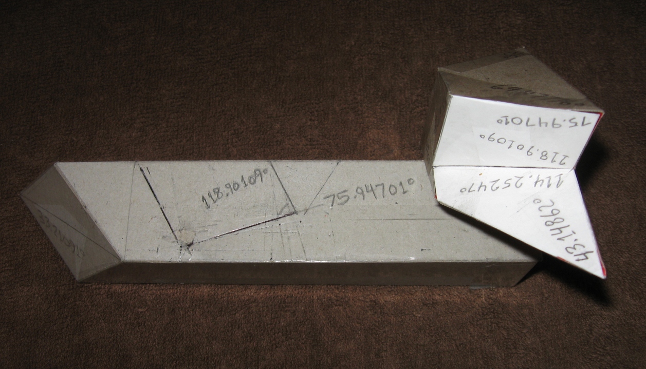
Sim ... I don’t have much time so just here are a few images for the time being in case anyone wants to make a cardboard model as a visual reference for further study. The blade bevels are indicated on the development so a model can be cut from wood if desired (the cutting will likely be with a hand saw, I can't see doing this with a compound miter saw).
The mathematical analysis to produce the model was thorough: linear algebra and vectors, slope-intercept equations of lines, trigonometry, geometry (especially the all important DP lines and the planes that generate them), compound angle formulas. Overall I'm satisfied with the math and pleased with the model and hopefully all the bugs and faults have been worked out. If the fit seems a bit sloppy in the photos it's because the two pieces aren't taped or glued together, one is just balancing on the other.
Now comes the hard part – writing this up in a comprehensible format in terms of the developmental geometry. Let’s see if we can turn Mr. Hyde back into Dr. Jekyll ...


No comments:
Post a Comment
Note: Only a member of this blog may post a comment.