Tuesday, February 5, 2013

8 Sided Polygon Rafter Table ( 8 - gon ) Octagon


8 Sided Polygon Rafter Table ( 8 - gon )

central angle = 45°
working angle = 22.5°
plan angle = 67.5°
miter angle = 4.97 & 12 (22.50°)
hip run per foot = 12.99
apothem multiplier = 1.08239
side wall multiplier = 0.82843
Pitch
Roof Angles
Frieze Block Angles
Hip Rafters
Jack Rafters
Roof Pitch
Angle
Hip Pitch
Angle
Angle
Saw Bevel
Side Cut
Angle
Backing Angle
Hip Drop
2x
Hip Drop
4x
Length
Per-FT
Side Cut
Angle
First
12” O.C.
First
16” O.C.
First
24” O.C.
Spaced
12” O.C.
Spaced
16” O.C.
Spaced
24” O.C.
Multiplier
0
0.00
0.00
0
22.5
22.50
0.00
0.00
0.00
12.99
22.5
30.63
40.29
59.60
28.97
38.63
57.94
2.41421
1
4.76
4.40
1.97
22.42
22.44
1.82
0.02
0.06
13.03
22.43
30.74
40.43
59.81
29.07
38.76
58.14
2.42258
2
9.46
8.75
3.90
22.18
22.26
3.61
0.05
0.11
13.14
22.22
31.05
40.84
60.42
29.37
39.16
58.74
2.44751
3
14.04
13.01
5.74
21.79
21.98
5.33
0.07
0.17
13.33
21.89
31.57
41.53
61.44
29.86
39.82
59.72
2.48851
4
18.43
17.12
7.46
21.29
21.60
6.95
0.10
0.22
13.59
21.45
32.29
42.47
62.83
30.54
40.72
61.08
2.54480
5
22.62
21.05
9.05
20.69
21.13
8.46
0.12
0.28
13.92
20.92
33.18
43.65
64.57
31.38
41.85
62.77
2.61540
6
26.57
24.79
10.49
20.02
20.61
9.85
0.14
0.33
14.31
20.33
34.25
45.04
66.64
32.39
43.19
64.78
2.69917
7
30.26
28.32
11.79
19.30
20.03
11.12
0.17
0.39
14.75
19.69
35.46
46.64
69.00
33.54
44.72
67.08
2.79494
8
33.69
31.63
12.94
18.57
19.43
12.26
0.19
0.45
15.25
19.02
36.82
48.42
71.63
34.82
46.42
69.64
2.90152
9
36.87
34.72
13.96
17.83
18.80
13.27
0.22
0.50
15.80
18.33
38.29
50.36
74.50
36.21
48.28
72.43
3.01777
10
39.81
37.59
14.85
17.10
18.17
14.18
0.24
0.56
16.39
17.65
39.87
52.44
77.59
37.71
50.28
75.42
3.14260
11
42.51
40.26
15.64
16.39
17.54
14.99
0.26
0.61
17.02
16.98
41.55
54.65
80.86
39.30
52.40
78.60
3.27505
12
45.00
42.73
16.32
15.70
16.92
15.70
0.29
0.67
17.68
16.32
43.32
56.98
84.29
40.97
54.63
81.94
3.41421
13
47.29
45.02
16.93
15.04
16.32
16.33
0.31
0.73
18.38
15.69
45.16
59.40
87.87
42.71
56.95
85.42
3.55932
14
49.40
47.15
17.46
14.42
15.73
16.89
0.33
0.78
19.10
15.09
47.07
61.91
91.58
44.52
59.35
89.03
3.70966
15
51.34
49.11
17.92
13.83
15.17
17.39
0.36
0.84
19.84
14.51
49.04
64.49
95.41
46.38
61.83
92.75
3.86463
16
53.13
50.93
18.33
13.27
14.63
17.83
0.38
0.89
20.61
13.96
51.05
67.15
99.34
48.28
64.38
96.57
4.02369
17
54.78
52.62
18.70
12.75
14.12
18.22
0.41
0.95
21.39
13.43
53.12
69.86
103.35
50.24
66.98
100.47
4.18638
18
56.31
54.19
19.02
12.26
13.62
18.57
0.43
1.00
22.20
12.94
55.22
72.63
107.45
52.23
69.64
104.45
4.35229
19
57.72
55.64
19.30
11.79
13.16
18.88
0.45
1.06
23.02
12.47
57.36
75.45
111.62
54.25
72.34
108.51
4.52106
20
59.04
57.00
19.55
11.36
12.71
19.16
0.48
1.12
23.85
12.03
59.54
78.31
115.85
56.31
75.08
112.62
4.69239
21
60.26
58.26
19.78
10.94
12.29
19.41
0.50
1.17
24.69
11.61
61.74
81.20
120.13
58.39
77.86
116.78
4.86600
22
61.39
59.44
19.98
10.56
11.89
19.63
0.53
1.23
25.55
11.22
63.97
84.14
124.47
60.50
80.67
121.00
5.04167
23
62.45
60.55
20.17
10.20
11.51
19.83
0.55
1.28
26.41
10.85
66.22
87.10
128.85
62.63
83.51
125.26
5.21918
24
63.43
61.58
20.33
9.85
11.15
20.02
0.57
1.34
27.29
10.49
68.50
90.09
133.28
64.78
86.37
129.56
5.39835

Framing Square usage Example: 8:12 Pitch
(Rafter Length Per Ft = 14.42) (Hip Rafter Length Per Ft = 15.25)
SS Angle = Speed Square Angle
Saw Angle produces compound Speed Square Angle
 
Tongue (8.00) Blade (12.00) for Rafter Plumb Cut Angle (SS Angle 33.69)
Tongue (12.00) Blade (8.00) for Rafter Level Cut Angle (SS Angle 56.31)
 
Tongue (8.00) Blade (12.99) for Hip Rafter Plumb Cut Angle (SS Angle 31.63)
Tongue (12.99) Blade (8.00) for Hip Rafter Level Cut Angle (SS Angle 58.37)
 
Tongue (5.38) Blade (15.25) for Hip Side Cut Angle (SS Angle 19.43) (Saw Angle 67.50)
Tongue (3.31) Blade (15.25) for Hip Backing Angle (SS Angle 12.26)
 
Tongue (4.97) Blade (14.42) for Jack Rafter Side Cut Angle (SS Angle 19.02) (Saw Angle 67.50)
 
Tongue (3.31) Blade (14.42) for Purlin Rafter Plumb Cut Angle (SS Angle 12.94) (Saw Angle 12.26)
Tongue (4.97) Blade (14.42) for Purlin Rafter Cross Cut Angle (SS Angle 19.02)
 
Tongue (3.31) Blade (14.42) for Roof Sheathing Plumb Cut Angle (SS Angle 12.94) (Saw Angle 12.26)
Tongue (4.97) Blade (14.42) for Roof Sheathing Cross Cut Angle (SS Angle 19.02)
 
Tongue (8.00) Blade (12.00) for Miter Box Gable Mould Plumb Cut Angle (SS Angle 33.69)
Tongue (8.00) Blade (12.99) for Miter Box 2 Cord Polygon Gable Mould Hip Plumb Cut Angle (SS Angle 31.63)
Tongue (4.97) Blade (12.00) for Miter Box 2 Cord Polygon Gable Mould Hip Cross Cut Angle (SS Angle 22.50) (Saw Angle 22.50)
 
Tongue (3.31) Blade (14.42) for Frieze Block Plumb Cut Angle (SS Angle 12.94)
Tongue (4.97) Blade (14.42) for Frieze Block Cross Cut Angle (SS Angle 19.02) (Saw Angle 18.57)
 
Tongue (3.31) Blade (14.42) for Square Cut Fascia Plumb Cut Angle (SS Angle 12.94)
Tongue (4.97) Blade (14.42) for Square Cut Fascia Cross Cut Angle (SS Angle 19.02) (Saw Angle 18.57)
 
Tongue (0.88) Blade (4.97) for Hip Rafter Square Cut Fascia Plumb Cut Angle (SS Angle 4.18)
Tongue (4.97) Blade (14.42) for Hip Rafter Square Cut Fascia Cross Cut Angle (SS Angle 19.02) (Saw Bevel Angle 18.57)

Roof Framing Polygon Angles


Laying Out Polygons

Although the carpenters framing square is particularly adapted for roof framing and is probably used more for roof framing work than for any other purpose, there are a great many other uses for the carpenters framing square. The carpenter that thoroughly understands the principle of the steel square will continually find new problems that can be solved with greater ease by the use of the steel square than by any other method.


Classification of Polygons.
A closed plane figure made up of several line segments that are joined together. The sides do not cross each other. Exactly two sides meet at every vertex. A regular polygon is a polygon whose sides are all the same length, and whose angles are all the same. The sum of the interior angles of a polygon with n sides, where n is 3 or more, is 360° degrees.

Polygons are classified according to the number of sides: A polygon of three sides is called a triangle; one of four sides, a quadrilateral; one of five sides, a pentagon; one of six sides, a hexagon; one of seven sides, a heptagon; one of eight sides, an octagon; one of nine sides, a nonagon;  one of ten sides, a decagon; one of eleven sides, an un-decagon; and one of twelve sides, a dodecagon; and one of thirteen sides, a tridecagon; and one of fourteen sides, a tetradecagon; and one of fifteen sides, a pentadecagon; and one of sixteen sides, a hexadecagon.

Regular polygon 3.svg
Equilateral
triangle

{3}
Regular polygon 4.svg
Square
quadrilateral
{4}
Regular polygon 5.svg
Pentagon
{5}
Regular polygon 6.svg
Hexagon
{6}
Regular polygon 7.svg
Heptagon
{7}
Regular polygon 8.svg
Octagon
{8}
Regular polygon 9.svg
Nonagon or enneagon
{9}
Regular polygon 10.svg
Decagon
{10}
Regular polygon 11.svg
Hendecagon
or un-decagon
{11}
Regular polygon 12.svg
Dodecagon
{12}
Regular polygon 13.svg
Tridecagon
{13}
Regular polygon 14.svg
Tetradecagon
{14}
Regular polygon 15.svg
Pentadecagon
{15}
Regular polygon 16.svg
Hexadecagon
{16}


Laying Out an Equilateral Triangle.
In the drawing below is shown an method of finding the angle of the sides and also the miter angle of a regular polygon of three sides. A regular polygon of three sides is an equilateral triangle, and


is consequently equiangular  that is, all sides are equal in length and the angles contain the same number of degrees. In the drawing above, A B represents the line on which the triangle is to be formed. Place the square so that 12 inches an the tongue and 20.79 inches on the body are over the line A B; then, the tongue will give the direction of one side of the triangle. By reversing the square so that the 12 inches is at A and the 20.79 inches is at B, the other side of the triangle may be drawn. The intersection of these two lines at C completes the equilateral triangle.

If a frame is to be constructed, the body of the square will give the direction to cut for a miter joint.


If a butt joint is required, the cut will be along the tongue, using the same figures on the square. The miter joint makes an angle of 30° with the sides, while the butt joint is parallel with the sides. The direction of these cuts can also be found by using 7 inches on the body and 4 inches on the tongue. While these figures are not absolutely correct, they are close enough for all practical purposes. They may be proved by using the proportion 20.79 ÷ 12 = 7 ÷ 4.04. It will therefore be seen that 4 inches is .04, or about 1/32, inch too short.


Laying Out a Regular Pentagon, or Five-Sided Polygon.
In the drawing below, A B C D E represents the outside of a pentagon.


To construct the pentagon, draw a line A b, and place the square on this line, as shown, with 11 inches on the body and 8 inches on the tongue. Mark along the tongue A E; then reverse the position of the square, as shown at ABb, and mark along the tongue A B. The two sides of the pentagon, or at least the direction of the two sides, will then be deter- mined. To find the direction of the side B C, erect a perpendicular to the line A E at 4, or the center of the line A E; then place the square as shown by the dotted lines. In the same manner, the direction of the other sides may be found; or, the direction and lengths may be found by the use of compasses.

In the next drawing it shows the method of using a steel square to find the miter and butt joints of a pentagon.


The same figures on the square that gave the directions of the sides in the previous drawing, that is, 11 inches and 8 inches, will also give the miter cut, the cut being along the 8-inch side. For the butt joint, take 12 inches and 3.9 inches, and cut on the 3.9 inches side.


Laying Out a Regular Hexagon, or Six-Sided Polygon.

The method of finding the direction of the sides of a regular hexagon is the same as that just described for a pentagon. The figures on a square to use for finding the sides of a hexagon are 12 inches and 6.93 inches, the figure last mentioned giving the direction.


In the drawing above, A B C D represents the outline of a hexagon. At A, B, and C are shown miter joints, and at D, E, and F, butt joints. Take 12 inches on the body and 6.93 on the tongue of the square, and mark along the tongue for both the miter and the butt joints. The whole numbers on the square that will give the hexagon cuts are 7 and 4, and the proportion 12 6.93 = 7 ÷ 4.04 will show how nearly correct these figures are. It will be seen from this proportion that if 7 and 4 are used, the 4 is short by .04, or about 1/32, inch. While this difference is very little for one cut, it should be remembered that as the number of sides increase, the error is multiplied by twice the number of sides. The polygon in question will have twelve cuts, and the difference for each cut, if 7 and 4 are used, will be 15°, and for twelve cuts it will be 12 x 15° = 180°, a 3° error. Therefore, instead of the sum of the interior angles of the hexagon being equal to 720°, it will be equal to 720° - 3° = 717°. Or, again, each angle of the hexagon is equal to 120° - 30°, or which is 119.5°.

Laying Out a Regular Heptagon, or Seven- Sided Polygon.


The same method employed for finding the direction of the sides in a pentagon or hexagon may be used for laying out a heptagon. In drawing above, A B C D E F G represents the outside of a regular heptagon. The angles at A, B, C, and D are miter joints, and those at E, F, and G are butt joints. The figures on the square that give the cuts for the miter joint are 12. and 5.78, the cut being on the 5.78-inch side. For the butt joint, take 12 and 9.57, and the 9.57-inch side gives the cut. The figures on the square that give the miter cuts for the heptagon are 14. and 7. These figures are very close, as will be seen by the proportion 12 ÷ 5.78 = 14.5 ÷ 6.984.

Laying Out a Regular Octagon, or Eight-Sided Polygon.


In the drawing above, A B C D E F G H represents the outside lines of an octagon. The figures on the square that give the miter cuts are 12 and 4.97, the cutting to be done on 4.97-inch side. The figures to use for butt joints are 12 and 12, or any equal distances from the heel on the tongue and the body of the square. In other words, the cut for a butt joint is a square miter. The whole numbers that give the octagon miter are 17 and 7. These figures are very nearly correct, as will be seen by taking 12 and 4.97, which are absolutely correct, and making the proportion 12 ÷ 4.97 = 17 ÷ 7.04. That is, if 17 is used, 7.04 will be correct. The difference in this case is not so great as would be supposed. To find just what the error will be, take the proportion 17 ÷ 7 = 12 ÷ 4.94 and compare it.


What is a Polygon Roof Miter Angle?
The polygon roof miter angle is the tangent of the polygon central angle divided by two. The central angle for an Octagon roof is 45°. One half of 45° is 22.5°. The tangent of 22.5° = .41421 Laying out an Octagon using a framing square we would take 12" on the blade and the number to be taken on the tongue is 12 * .41421, which is 4.97" , or nearly 5".

How to draw any polygon with an compass & straight edge.


Rafter Tools App


Polygon  Length Dimension
Select the Length input type from the menu option.

  1. Imperial/English Inch base 12
  2. Metric using mm
  3. Decimal Inch base 10


Polygon  Length Type
This menu option allows you to select different parts of the polygon for calculating the angles and dimensions of the polygon.

  1. Common Rafter Run
  2. Side Wall Length
  3. Half of Side Wall Length
  4. Radius
  5. Hip Rafter Run
  6. Hip Rafter Length
  7. Common Rafter Length
  8. Circumscribed to Radius
  9. Inscribed to Radius


Roof Pitch Angle
Select the input type from the input menu,

  1. Imperial/English Inch base 12 — default, enter lengths in inches like 12, 
  2. Metric 300mm base, enter millimeters like 300 
  3. Decimal Inch base 10 — enter base 10 decimal numbers for the length


Jack Rafter Spacing
Enter the jack rafter on center spacing.

Overhang Run
Enter the common rafter overhang run.

Polygon Number Sides.
Select the number of sides of the polygon. From 3 - 96.

The output mode selection can be completely different from the input mode Output Menu Mode

  1. Imperial/English Inch base 12 —default.. use American standard pitches over 12.
  2. Metric 300mm base — 300mm is 11.81102 inches, similar usage to the American framing squares.
  3. Decimal Inch base 10 — use this option when working with tangents or using the Chappell Master Framing Square.


8:12 pitch and 112" side wall length example Octagon (8 sides)


Use the email function in Rafter Tools to send yourself an email of the calculated results. It will look something like this.
Rafter Tools -- Polygon Rafters Calculations

Polygon Eave Angle
150.00°
Polygon Plan Angle
75.00°
Polygon Miter Angle
15.00
Side Wall Length
74 9/16''in
Half of Side Wall Length
37 1/4''in
Roof Pitch Angle
45.00°
Roof Pitch
12  in\12in
Rafter Run
139 1/16''in
Rafter Length
196 11/16''in
Rafter Overhang Length
33 15/16''in
Polygon Hip Rafter Angle
44.01°
Polygon Hip Rafter Pitch
12  in\12 7/16in
Hip Rafter Run
144 ''in
Hip Rafter Length
200 3/16''in
Hip Rafter Overhang Length
34 9/16''in
Jack Rafter Length Difference @ 16.00
84 7/16''in
Theoretical Common Rafter Rise
139 1/16''in


Monday, February 4, 2013

Compound Miter Angle and Bevel Angle Calculator

Crown Molding Tools Compound Miter Angle and Bevel Angle Calculator for compound joinery.
Use this calculator to cut compound angles with the material on edge in the compound miter saw instead of laying flat in the compound miter saw.


Compound Miter Angle and Bevel Angle Calculator Input variables
  1. Miter Angle for Material Laying Flat in the Compound Miter Saw
  2. Saw Blade Bevel Angle for Material Laying Flat in the Compound Miter Saw

Calculated Results for the Compound Miter Angle and Bevel Angle Calculator

  • Miter Angle to cut  the Material On Edge in the Compound Miter Saw
  • Saw Blade Bevel Angle to cut  the Material On Edge in the Compound Miter Saw


There are three ways of cutting crown molding.
  1. Material laying flat in the compound miter saw .
  2. Material on edge in the compound miter saw.
  3. Material nested in the compound miter saw. (Up-side down and backwards)

Material Laying flat in the Compound Miter Saw.

Material Laying flat in the Compound Miter Saw.


Material On Edge in the Compound Miter Saw.


Some times the miter angle or saw blade bevel angle is beyond the capabilities of the compound miter saw.  Or it's just easier to cut the material on edge instead of laying flat in the compound miter saw.

Example of cutting the tetrahedron platonic solid.


Settings for Cutting the Material Laying Flat in the Compound Miter Saw
Saw Miter Angle = 54.7356°
Saw Blade Bevel Angle = 30.0000°

Settings for Cutting  the Material On Edge in the Compound Miter Saw
Top Edge of Hip Rafter Saw Miter Angle = 45.000°
Top Edge of Hip Rafter Saw Blade Bevel Angle = 45.00°


The tetrahedron platonic solid material is cut on edge.


You can use this calculator to cut any type of  material . It is not limited to crown molding on edge. I use it all the time to cut purlin rafters, the compound joinery of the platonic solids and the compound joinery of Archimedean Solids.


Saturday, February 2, 2013

Regulating lines of Geometry Without the Assistance of Real Numbers

I've been  following Jane Griswold Radocchia ,Architect, blog on regulating lines of geometry . She asked me to expand on my comment on her blog Carpenter squares in1503.

My comment:

Jane,

What's fun about these drawings are the platonic solids on the table in the drawing. John Brown, 1661, also had the platonic solids in his portrait/drawing with his carpenter's rule/square.

A Note on the Wooden Carpenter’s
Rule from Odyssey Shipwreck Site 35F

http://www.shipwreck.net/pdf/OMEPaper10_000.pdf

Sim

Expanding on my comment:


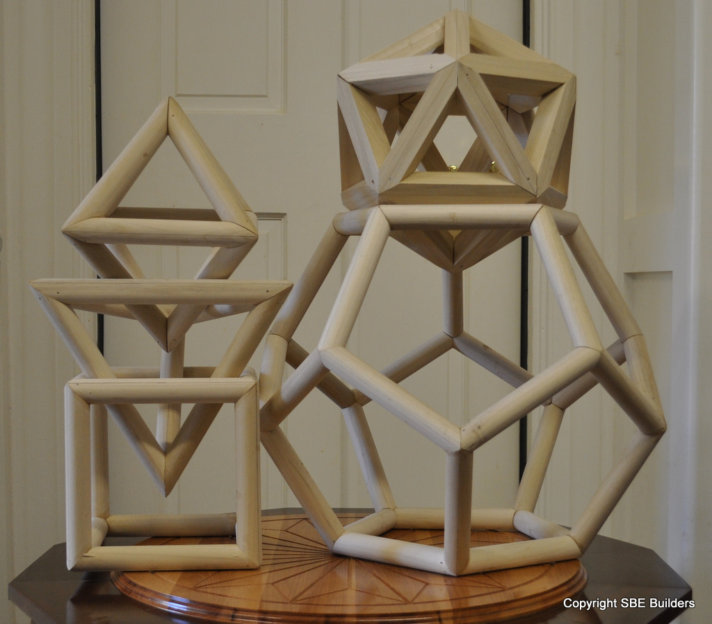
There are exactly five regular polyhedra (platonic solids).
Euclid's book of Elements book XIII

The 5 Platonic solids: 
The Tetrahedron (3 equilateral triangles at each vertex) 
The Hexahedron (3 squares at each vertex, cube) 
The Octahedron (4 equilateral triangles at each vertex) 
The Dodecahedron (3 pentagons at each vertex) 
The Icosahedron (5 equilateral triangles at each vertex) 


Compound Saw Miter and Saw Blade Bevel angles for building the 5 Platonic Solids out of wood Wood polyhedron or Wooden Polyhedra


John Brown an mathematical instrument maker, 1661, had the platonic solids in his portrait/drawing with his carpenter's rule/square.

John Brown portrait with the platonic solids.


Pepys worked with John Brown to design a custom-made rule, which Pepys called the “most useful that ever was made, and myself had the honor of being as it were the inventor of this form of it.”

The Diary of Samuel Pepys

The mathematical practitioners of the seventeenth century all subscribed to the Vitruvian   vision of  the architect as a geometrical paragon. With the platonic solids in the drawings/ portraits it showed how the  mathematical practitioners studied Euclid's books of  Elements.  The mathematical practitioners were in the process of developing Analytic geometry, ( Descartes. In Book III of La Géométrie ) but wanted to show how their mathematical instruments were based on solid geometry already proven by Euclid's propositions.

Elucidation of the stuff is self evident. 
We hold these truths to be self-evident , and need no further explanation. 
Stuff = roof framing geometry
Stuff = tangent handrailing geometry
Stuff = Regulating lines of Geometry
Stuff = Ad Quadratum , square rotated in circle
Stuff = Ad Triangulum , 
Stuff = Daisy Wheel

Architecture and Mathematical Practice in England, 1550-1650


The mathematical practitioners wanted to introduce to the English skills that were monopolized by foreigners.  This must be in reference to the  Islamic Moors . Such as the Alhambra, Granada Spain.

The roof over the Hall of the Abencerrajes is unique because the roof actually follows the Ad Quadratum ground plan that is used to develop the octagonal ground plan. Squares rotated in the circle.