Equal Pitched Roof 6:12
Hip Rafter Width = 3.5"
Rafter Width = 1.5"
I'll use use my Android Rafter Tools app and my Rafter Tools+ for iPhone app to check the calculations I come up with using geometry and trigonometry.
What are the Valley Jack Rafter Lengths for A & B ?
What are the Valley Jack Rafter Slider (Doppelschifter )Lengths for Jack Rafters C, D & E ?
What are the Hip Rafter Lengths for the Bay Window Hip Rafters A & B & the Cripple Hip Rafter ?
What is the Miter & Edge Bevel Angles for the California Valley Rafter Sleeper?
What is the Valley Rafter Slope Angle for the Dog Leg Valley ?
What are the Frieze Block Angles ?
What are the Purlin Miter & Bevel & Lip Cut Angles ?
What are the Hip Rafter Diamond Post Miter & Bevel Angles ?
What are the King Common Rafter Lengths per structural Detail 1?


Complex Roof Framing Kernel based on a Prism, the unbacked shoulder of the Hip Rafter

Roof Framing Geometry Kernel rafter lengths roof ratio multiplier.
The common rafter length can be calculated by the roof ratio length per 12" of run. Divide the rafter length by 12" of run to calculate the roof ratio multiplier.
Hip Rafter Ratio Length Multiplier
HRRLM = 18 ÷ 12 = 1.5
Common Rafter Length Multiplier
CRLM = 13.4164 ÷ 12 = 1.11803

King Common Rafter Length
6:12 Pitch
For the Common Rafter Length to the Ridge
[Decimal Inch] 177.25" x tan (48.18968°) = 198.17148" FL
What are the Valley Jack Rafter Lengths for A & B ?
What are the Valley Jack Rafter Slider (Doppelschifter )Lengths for Jack Rafters C, D & E ?
What are the Hip Rafter Lengths for the Bay Window Hip Rafters A & B & the Cripple Hip Rafter ?
What is the Miter & Edge Bevel Angles for the California Valley Rafter Sleeper?
What is the Valley Rafter Slope Angle for the Dog Leg Valley ?
What are the Frieze Block Angles ?
What are the Purlin Miter & Bevel & Lip Cut Angles ?
What are the Hip Rafter Diamond Post Miter & Bevel Angles ?
What are the King Common Rafter Lengths per structural Detail 1?


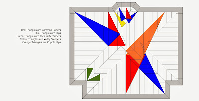
Using Geometry, draw out the triangles representing each framing member to calculate-dimension all of the theoretical lengths of the rafters. You could layout the roof full scale with each framing member drawn to it's actual width if the walls are not yet framed.
- Red Triangles are Common Rafters
- Blue Triangles are Hips
- Green Triangles are Jack Rafter Sliders
- Yellow Triangles are Valley Sleepers
- Orange Triangles are Cripple Hips

There are a lots of ways of calculating the common rafter lengths and the hip/valley rafter lengths.
- Using Geometry
- Radford's Cyclopedia Of Construction
- Roof Framing by H.H. Siegele
- Steel Square by Gilbert Townsend
- Practical Use Of the Steel Square by Fred Hodgson
- Handbook of Carpentry and Joinery by A.B. Emary
- American Carpenter And Builder Magazine
- Carpenter's Framing Square
- Chappell Master Framing Square
- Advanced Timber Framing by Steve Chappell
- When Roofs Collide by Will Beemer
- Timber Framing Guild Publications
- Full Length Roof Framer by A.J. Riechers
- Roof Framer by Marshall Gross
- Roof Framer's Bible by Barry Mussell
- The Rafter Book by David McIntire
- A Roof Cutter's Secrets by Will Holladay
- A Scientific Calculator
- A Graphing Calculator like the HP 50g
- Construction Master Calculator
- Joe Bartok's Online Framing Calculators
- Greg Tarrant's Online Framing Calculators
- BuildCalc app for Android & iPhone
- Rafter Tools app for Android
- Rafter Tools+ app for iPhone
- Basiswissen Schiten
- Grundwissen des Zimmerers
- La Charpente en Bois by Emery
- Complex Roof Framing by Billy Dillon
- Framing a Hip Roof by Tim Uhler
- Trigonometry
Example using Geometry
 |
| Standard Roof Framing Kernel |
 |
| Tetrahedron Roof Framing Kernel |
Complex Roof Framing Kernel based on a Prism, the unbacked shoulder of the Hip Rafter

The common rafter length can be calculated by the roof ratio length per 12" of run. Divide the rafter length by 12" of run to calculate the roof ratio multiplier.
Hip Rafter Ratio Length Multiplier
HRRLM = 18 ÷ 12 = 1.5
Common Rafter Length Multiplier
CRLM = 13.4164 ÷ 12 = 1.11803
King Common Rafter Length TL
[Decimal Inch] 178" x 1.11803 = 199.00934" TL
Hip Rafter Length TL
[Decimal Inch] 178" x 1.5 = 267" TL

Example using trigonometry
TL = Theoretical Length or True Length of Rafter
TL = Theoretical Length or True Length of Rafter
FL = Framing - Cut Length of Rafter
King Common Rafter Length
6:12 Pitch
Plan Angle = 45°
Rafter Slope Angle 26.56505°
Rafter Slope Angle 26.56505°
Hip Rafter 6:17 or 6:16.97 or 19.47122°
14'-10" Common Rafter Run
or
14'-9 1/4" Common Rafter Run to the Ridge
King Common Rafter Length TL
14'-10" Common Rafter Run
or
14'-9 1/4" Common Rafter Run to the Ridge
King Common Rafter Length TL
Common Rafter Run ÷ cos ( Roof Slope Angle )
[Feet Inches] 14'-10" ÷ cos (26.56505°) = 16'-7" TL
[Feet Inches] 14'-10" ÷ cos (26.56505°) = 16'-7" TL
[Decimal Inch] 178" ÷ cos (26.56505°) = 199.01005 TL
King Common Rafter Length To the Ridge FL
Common Rafter Run To the Ridge ÷ cos ( Roof Slope Angle )
[Feet Inches] 14'-9 1/4" ÷ cos (26.56505°) = 16' 6 3/16" FL
[Decimal Inch] 177.25" ÷ cos (26.56505°) = 198.1715" FL
[Feet Inches] 14'-9 1/4" ÷ cos (26.56505°) = 16' 6 3/16" FL
[Decimal Inch] 177.25" ÷ cos (26.56505°) = 198.1715" FL
Theoretical Hip Rafter Run
Common Rafter Run ÷ cos ( Plan Angle )
[Feet Inches] 14'-10" ÷ cos (45°) = 20'-11 3/4"
[Decimal Inch] 178" ÷ cos (45°) = 251.73001"
Hip Rafter Run To Ridge
Common Rafter Run To Ridge ÷ cos ( Plan Angle )
[Feet Inches] 14'-9 1/4" ÷ cos (45°) = 20'-10 11/16"
[Decimal Inch] 177.25" ÷ cos (45°) = 250.66935"
Hip Rafter Length TL
Hip Rafter Run ÷ cos ( Hip Rafter Slope Angle )
[Feet Inches] 20'-11 3/4" ÷ cos (19.47122°) = 22'-3" TL
[Decimal Inch] 251.73001" ÷ cos (19.47122°) = 266.99999" TL
[Feet Inches] 20'-11 3/4" ÷ cos (19.47122°) = 22'-3" TL
[Decimal Inch] 251.73001" ÷ cos (19.47122°) = 266.99999" TL
Hip Rafter Length To The Ridge FL
Hip Rafter Run to the Ridge ÷ cos ( Hip Rafter Slope Angle )
[Feet Inches] 20'-10 11/16" ÷ cos (19.47122°) = 22'-1 7/8" FL
[Decimal Inch] 250.66935" ÷ cos (19.47122°) = 265.87499" FL
I think the easiest way to calculate the lengths of the Common Rafter, Hip Rafter and Jack Rafter Difference is to use the roof sheathing angle.
Roof Sheathing Angle = arctan (tan Plan Angle ÷ cos Common Rafter Slope Angle)
Roof Sheathing Angle = arctan (tan 45° ÷ cos 26.56505°)
48.18968° = arctan (tan 45° ÷ cos 26.56505°)
The tan of 45° = 1, so you can 1÷ cos Common Rafter Slope Angle
or in this example
48.18968° = arctan (1 ÷ cos 26.56505°)
[Feet Inches] 20'-10 11/16" ÷ cos (19.47122°) = 22'-1 7/8" FL
[Decimal Inch] 250.66935" ÷ cos (19.47122°) = 265.87499" FL
I think the easiest way to calculate the lengths of the Common Rafter, Hip Rafter and Jack Rafter Difference is to use the roof sheathing angle.
Roof Sheathing Angle = arctan (tan Plan Angle ÷ cos Common Rafter Slope Angle)
Roof Sheathing Angle = arctan (tan 45° ÷ cos 26.56505°)
48.18968° = arctan (tan 45° ÷ cos 26.56505°)
The tan of 45° = 1, so you can 1÷ cos Common Rafter Slope Angle
or in this example
48.18968° = arctan (1 ÷ cos 26.56505°)
For the Common Rafter Length to the Ridge
[Decimal Inch] 177.25" x tan (48.18968°) = 198.17148" FL
For the Hip Rafter Length to the Ridge
[Decimal Inch] 177.25" ÷ cos (48.18968°) = 265.87497" FL
For the Jack Rafter Length Difference
[Decimal Inch] 24" x tan (48.18968°) = 26.83281"

For the Cripple Hip Rafter Length TL
First calculate the hip rafter length for the 14'-8" run
[Decimal Inch] 178" ÷ cos (48.18968°) = 266.99999" TL

Roof Sheathing Angle = arctan (tan Plan Angle ÷ cos Common Rafter Slope Angle)
Roof Sheathing Angle = arctan (tan 59.03624° ÷ cos 26.56505°)
61.77948° = arctan (tan 59.03624° ÷ cos 26.56505°)

For the King Common Rafter Length
(Ridge Width x 0.5) x tan (Plan Angle) = Ridge Deduction in Plan View


Roof Sheathing Angle = arctan (tan 45° ÷ cos 26.56505°)
48.18968° = arctan (tan 45° ÷ cos 26.56505°)
Valley Sleeper Miter Angle at the Top of the Sleeper = Jack Rafter Side Cut Angle = 41.81031°
Valley Sleeper Miter Angle at the Foot of the Sleeper = Roof Sheathing Angle = 48.18968°
Valley Sleeper Saw Blade Bevel Angle = arctan(tan(90° - Main Roof Pitch°) x cos(Main Roof Sheathing Angle))
Valley Sleeper Saw Blade Bevel Angle = arctan(tan(90° - 26.56505°) x cos(48.18968°)) = 53.13010°


For the Purlin Miter & Back Bevel angles you can use geometry or trigonometry.

Example using geometry for the Purlin Miter angle. The Purlin Back Bevel Angle on the top edge of the purlin is the same as the Jack Rafter Side Cut angle. Or sometimes referred to as the top cut angle in Timber Framing.

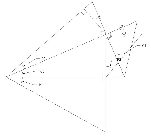
Example using the geometry of a tetrahedron for the Purlin Miter angle, Purlin Back Bevel Angle and the Purlin Saw Blade Bevel Angle.

Purlin Miter Angle = arctan( sin ( Pitch Angle ) ÷ tan( Plan Angle ))
Purlin Miter Angle = arctan( sin ( 26.56505 ) ÷ tan( 45 ))= 24.09484°


[Decimal Inch] 177.25" ÷ cos (48.18968°) = 265.87497" FL
For the Jack Rafter Length Difference
[Decimal Inch] 24" x tan (48.18968°) = 26.83281"
For the Jack Rafter Spacing Marks on the Hip Rafter
[Decimal Inch] 24" ÷ cos (48.18968°) = 35.99999"
For the Purlin Mark on the Hip Rafter
[Decimal Inch] 24" ÷ cos (48.18968°) = 35.99999"
For the Purlin Mark on the Hip Rafter
Run To Purlin in Plan View ÷ cos (48.18968°) = Purlin Mark on the Hip Rafter

First calculate the hip rafter length for the 14'-8" run
[Decimal Inch] 178" ÷ cos (48.18968°) = 266.99999" TL
Next calculate the hip rafter length for the 16'-10 1/4" run
[Decimal Inch] 202.25" ÷ cos (48.18968°) = 303.37496" TL
[Decimal Inch] 202.25" ÷ cos (48.18968°) = 303.37496" TL
Cripple Hip Rafter Length TL = 303.37496" - 266.99999" = 36.37506" TL
or use the common rafter runs to calculate the cripple hip rafter length
202.25 - 178 = 24.25" Run for the cripple hip rafter
24.25 ÷ cos (48.18968°) = 36.37499" TL
deduct the ridge thickness for both ridges, 0.75 + 0.75 = 1.5
24.25" - 1.5" ÷ cos (48.18968°) = 34.12499" FL
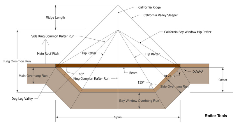
The Bay Window pop-out can be framed 5 or 6 different ways, with the hip rafters offset from the corner for an equal overhang, but with exposed frieze blocks it's easier to leave the Bay Window hip rafters centered on the 45° Bay Window pop-out walls. The Bay Window King Common Rafter Pitch is the same as the rest of the roof and has the same overhang run on the Bay Window Front Wall. Use the Span of the Bay Window to calculate the rise of the Bay Window roof. In this example the pitch is 6:12 and the Span is 10'-0", the offset is 24" and the Bay Window Front Wall Length is 72". First calculate the Bay Window plan angles. The eave angle is 135°.
Bay Window Plan Angles
Front Wall Plan Angle = arctan( 60" ÷ 36" ) = 59.03624°
Side Wall Plan Angle = 135° - 59.03624° = 75.96375°
Hip Rafter Slope Angle A & B
Hip Rafter Slope Angle = arctan (tan Common Rafter Pitch Angle × sin Plan Angle)
Hip Rafter Slope Angle = arctan (tan 26.56505° × sin 59.03624°) = 23.20706°
Roof Sheathing Angle = arctan (tan 59.03624° ÷ cos 26.56505°)
61.77948° = arctan (tan 59.03624° ÷ cos 26.56505°)
For the Common Rafter Length
[Decimal Inch] 36" x tan (61.77948°) = 67.08204" TL
[Decimal Inch] 36" x tan (61.77948°) = 67.08204" TL
For the Hip Rafter Length
[Decimal Inch] 36" ÷ cos (61.77948°) = 76.13146" TL
For the Hip Rafter Length To The Ridge
[Decimal Inch] 35.25" ÷ cos (61.77948°) = 74.54537" FL
For the Jack Rafter Length Difference
[Decimal Inch] 24" x tan (61.77948°) = 44.72135"
[Decimal Inch] 36" ÷ cos (61.77948°) = 76.13146" TL
For the Hip Rafter Length To The Ridge
[Decimal Inch] 35.25" ÷ cos (61.77948°) = 74.54537" FL
For the Jack Rafter Length Difference
[Decimal Inch] 24" x tan (61.77948°) = 44.72135"

(Ridge Width x 0.5) x tan (Plan Angle) = Ridge Deduction in Plan View
(1.5 x 0.5) x tan (59.03624) = 1.25"
[Decimal Inch] 60" - 1.25" ÷ cos (26.56505°) = 65.68449" FL

For the Side Wall King Common Rafter Slope Angle
Side Wall Plan Angle = 75.96375°
Hip Rafter Slope Angle = 23.20706°
Side Wall Length = 24" ÷ cos( 45° ) = 33.94113"
Side Wall King Common Rafter Slope Angle = arctan (tan Hip-Valley Pitch Angle ÷ sin Plan Angle)
Side Wall King Common Rafter Slope Angle = arctan (tan 23.20706° ÷ sin 75.96375°) = 23.84263°
Side Wall King Common Rafter Run = (0.5 x Side Wall Length) x tan ( Plan Angle)
Side Wall King Common Rafter Run = 16.97056" x tan ( 75.96375°) = 67.88222"
Side Wall King Common Rafter Length = 67.88222" ÷ cos ( 23.84263°) = 74.21586" TL
To calculate the actual Framing Length of the Side Wall King Common Rafter you need to calculate the dimension from the edge of the hip rafter at the plate line to the center of the side Wall King Common Rafter Run.
Side Wall Roof Sheathing Angle = arctan (tan 75.96376° ÷ cos 23.84263°) = 77.11992°
Hip Rafter Width ÷ sin(75.96376°) = 1.54616
33.94113" - 1.54616" = 32.39496"
32.39496" ÷ 2 = 16.19748"
Side Wall King Common Rafter Length = 16.19748" x tan ( 77.11992°) = 70.83506" FL

For the Cheek Cuts on the Side Wall King Common Rafter
Side Wall King Common Plumb Line Shift
(Rafter Width x 0.5) x tan (Plan Angle)
0.75 x tan (75.96376°) = 3.00"
Mark the plumb cut on the rafter and measure perpendicular to the plumb line using the Plumb Line Shift dimension and mark the second plumb line on the side of the rafter. Set the saw blade bevel angle to the plan angle to cut the rafter from the side of the rafter. Or set your saw to 90° - plan angle to run the saw down the face of the rafter plumb cut.


The head cuts on the Bay Window hip rafters always present a problem with the cheek cut angles. Sometimes it's best to draw out the ridge connections full scale to transfer the shifted plumb lines to the sides of the hip rafter, so you can mark off the back bevel angles of the cheek cuts to determine the angles. Then there's the problem of the length of the hip rafter cheek cuts. I've use my swing table, 10" blade, to cut the cheek cuts or you can use a BigFoot or Beam Saw to cut the 3" to 4" long cheek cuts. Most of the time I'll cut the hip rafter cheek cut on the plumb face of the hip rafter. Set your saw to 90° - plan angle and cut the hip rafter down the face of the plumb cut.
Saw Blade Bevel Angle on Side Of Hip Rafter 59.03625°... plan angle
Saw Blade Bevel Angle on Face Of Hip Rafter 30.96376°... 90° - plan angle
Saw Blade Bevel Angle on Side Of Hip Rafter 64.0664°.... planing angle of the 2 hip rafters in plan view.
Saw Blade Bevel Angle on Face Of Hip Rafter 25.93360°... 90° - planning angle


The HAP at the foot of the hip rafter also presents a problem with the unequal heel heights on each side of the hip rafter for roof plane alignment, since we're not using hip rafter offset/shift at the foot of the hip rafter. Most of the time the heel height difference is less than an 1/8". So it best to use the front wall heel height for the roof plane alignment height.


For the California Bay Window Hip Rafter you need to install the valley sleeper first. The edge bevel of the valley sleeper can be found from using geometry.

Or you can use trigonometry.
48.18968° = arctan (tan 45° ÷ cos 26.56505°)
Valley Sleeper Miter Angle at the Top of the Sleeper = Jack Rafter Side Cut Angle = 41.81031°
Valley Sleeper Miter Angle at the Foot of the Sleeper = Roof Sheathing Angle = 48.18968°
Valley Sleeper Saw Blade Bevel Angle = arctan(tan(90° - Main Roof Pitch°) x cos(Main Roof Sheathing Angle))
Valley Sleeper Saw Blade Bevel Angle = arctan(tan(90° - 26.56505°) x cos(48.18968°)) = 53.13010°
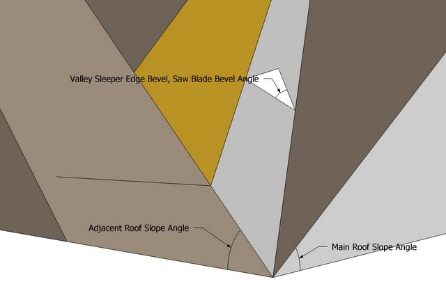

California Bay Window Hip Rafter Planning Point on Valley Sleeper. For the length of the California Bay Window Hip Rafter use my Rafter Tools app or pull out your tape measure and measure it.... Way too much math to explain here on the internet for this California Bay Window Hip Rafter length.

For the Purlin Miter & Back Bevel angles you can use geometry or trigonometry.

Example using geometry for the Purlin Miter angle. The Purlin Back Bevel Angle on the top edge of the purlin is the same as the Jack Rafter Side Cut angle. Or sometimes referred to as the top cut angle in Timber Framing.

Example using the geometry of a tetrahedron for the Purlin Miter angle, Purlin Back Bevel Angle and the Purlin Saw Blade Bevel Angle.

Example using Trigonometry to calculate the purlin miter & saw blade bevel angles.
Purlin Miter Angle = arctan( sin ( Pitch Angle ) ÷ tan( Plan Angle ))
Purlin Miter Angle = arctan( sin ( 26.56505 ) ÷ tan( 45 ))= 24.09484°
Purlin Saw Bevel Angle = arcsin( cos ( Pitch Angle ) x cos( Plan Angle ))
Purlin Saw Bevel Angle = arcsin( cos ( 26.56505 ) x cos( 45 )) = 39.23152°
The frieze block angles for frieze block #5 are the same as the purlin angles, because of the 90° eave angle and the equal pitched roof.
Purlin = Frieze Block = Square Tail Fascia = Crown Molding Angles
Frieze Block # 1 & 4
Frieze Block # 2 & 3
For the Purlin Lip Cut Angle
Purlin Lip Cut Angle = arctan( tan (Hip Rafter Backing Angle) x cos( Jack Rafter Side Cut Angle )) Purlin Lip Cut Angle = arctan( tan ( 18.43495 ) x cos( 41.81032 )) = 13.95274°
The geometry for the purlin lip cut is the same as the purlin claw. The only difference is the height of the material above the purlin claw.


Hip Rafter Diamond Post Miter Angle = arctan( tan( hip rafter slope angle ) x cos (plan angle)) =14.03624°
Hip Rafter Diamond Post Saw Blade Bevel Angle = arctan( sin( Diamond Post Miter Angle ) x tan (Plan Angle))= 13.63302°
Purlin Saw Bevel Angle = arcsin( cos ( 26.56505 ) x cos( 45 )) = 39.23152°
The frieze block angles for frieze block #5 are the same as the purlin angles, because of the 90° eave angle and the equal pitched roof.
Purlin = Frieze Block = Square Tail Fascia = Crown Molding Angles
Frieze Block # 1 & 4
Purlin Miter Angle = arctan( sin ( 26.56505 ) ÷ tan( 59.03624° ))= 15.02025°
Purlin Saw Bevel Angle = arcsin( cos ( 26.56505 ) x cos( 59.03624° )) = 27.39866°
Frieze Block # 2 & 3
Purlin Miter Angle = arctan( sin ( 23.84263° ) ÷ tan( 75.96376°° ))= 5.77051°
Purlin Saw Bevel Angle = arcsin( cos ( 23.84263° ) x cos( 75.96376°° )) = 11.36991°
Dog leg valley run = overhang_run /cos(90-main_plan_angle)
Dog leg valley run = 24 /cos(90-59.03624) = 27.98857
Dog leg valley slope angle = atan(overhang_rise / Dog leg valley run)
Dog leg valley slope angle = atan(12 / 27.98857) = 23.20706
Dog leg valley run = 24 /cos(90-59.03624) = 27.98857
Dog leg valley slope angle = atan(overhang_rise / Dog leg valley run)
Dog leg valley slope angle = atan(12 / 27.98857) = 23.20706
For the Purlin Lip Cut Angle
Purlin Lip Cut Angle = arctan( tan (Hip Rafter Backing Angle) x cos( Jack Rafter Side Cut Angle )) Purlin Lip Cut Angle = arctan( tan ( 18.43495 ) x cos( 41.81032 )) = 13.95274°
The geometry for the purlin lip cut is the same as the purlin claw. The only difference is the height of the material above the purlin claw.
Purlin Claw


Hip Rafter Diamond Post Miter Angle = arctan( tan( hip rafter slope angle ) x cos (plan angle)) =14.03624°
Hip Rafter Diamond Post Saw Blade Bevel Angle = arctan( sin( Diamond Post Miter Angle ) x tan (Plan Angle))= 13.63302°

Jack Rafter Lengths
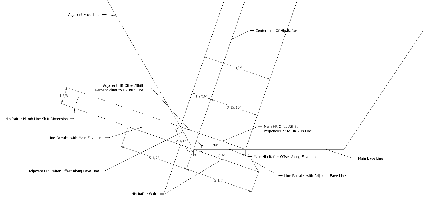
I like to calculate all of my Jack Rafter Lengths using the Roof Sheathing Angle. First you need to calculate the Hip Rafter Offset Along the Eave Line. With equal pitched roofs, on a 90° eave angle, the Hip Rafter Offset Along the Eave Line is the same dimension for all roof pitches.
.
Hip Width x cos (45°) = Hip Offset Along Eave Line
3.5" x cos (45°) = 2.4749"
Hip Offset Along Eave Line = 2.4749"
First Jack Rafter Length
Jack Rafter Spacing + (1/2 of Jack Rafter Width) - Hip Offset Along Eave Line = First Jack Rafter Run
First Jack Rafter Run x tan( Roof Sheathing Angle ) = First Jack Rafter Length
22.2751" x tan(48.18968°) = 24.9043"

Jack Rafter Length Deduction for Hip Rafter
Hip Offset Along Eave Line x tan(Roof Sheathing Angle) = Jack Rafter Length Deduction for Hip Rafter
Hip Offset Along Eave Line = 2.4749"
2.4749" x tan(48.18968°) = 2.7670"
Jack Rafter Length Deduction for Hip Rafter = 2.7670"
King Common Rafter Length = 199.0101" TL
King Common Rafter Length To Hip Rafters = 199.0101" - 2.7670" = 196.2431" FL
First Jack Rafter Length From King Common
23.25 x tan(48.18968°) = 25.9943"
196.2431" - 25.9943" = 170.2488" FL

Theoretical Length of Jack Rafter Slider "C"
Jack Rafter Run ÷ cos(Roof Slope Angle)
66" ÷ cos(26.56505°) = 73.79024" TL
Framing Length of Jack Rafter Slider (Doppelschifter )
Theoretical Length of Jack Rafter Slider - (Hip Rafter Deduction on Real Roof Surface x 2)
73.79024 - (2 x 2.7670") = 68.2563" FL for Slider "C"

Theoretical Length of Jack Rafter Slider D
Jack Rafter Run ÷ cos(Roof Slope Angle)
69.4359"" ÷ cos(26.56505°) = 77.63169" TL
Framing Length of Jack Rafter Slider
Theoretical Length of Jack Rafter Slider - (Hip Rafter Deduction on Real Roof Surface x 2)
77.63169 - (2 x 2.7670") = 72.09769" FL for Slider D
For the King Common Jack Rafter Length
Jack Rafter Slider Run ÷ cos ( Roof Slope Angle) = King Common Jack Rafter Length TL
66 ÷ cos(26.56505°) = 73.79024" TL
King Common Jack Rafter Length TL - Hip Rafter Deduction on Real Roof Surface
73.79024 - 2.7670" = 71.02324" FL
Jack Rafter Length Difference = 26.83281"
Jack Rafter "A" Length =
71.02324" - 26.83281" = 44.190432" FL

Using Geometry on the Real Roof Surface for the length of Jack Rafter "A"

For Jack Rafter "B"
For the King Common Jack Rafter Length
Jack Rafter Slider Run ÷ cos ( Roof Slope Angle) = King Common Jack Rafter Length TL
69.4359 ÷ cos(26.56505°) = 77.63169" TL
King Common Jack Rafter Length TL - Hip Rafter Deduction on Real Roof Surface
77.63169 - 2.7670" = 74.86469" FL

Jack Rafter "B" Length Trigonometry???
It's better to layout Jack Rafter B using geometry or layout the roof full scale.