Wednesday, November 6, 2013

European Task Model #3

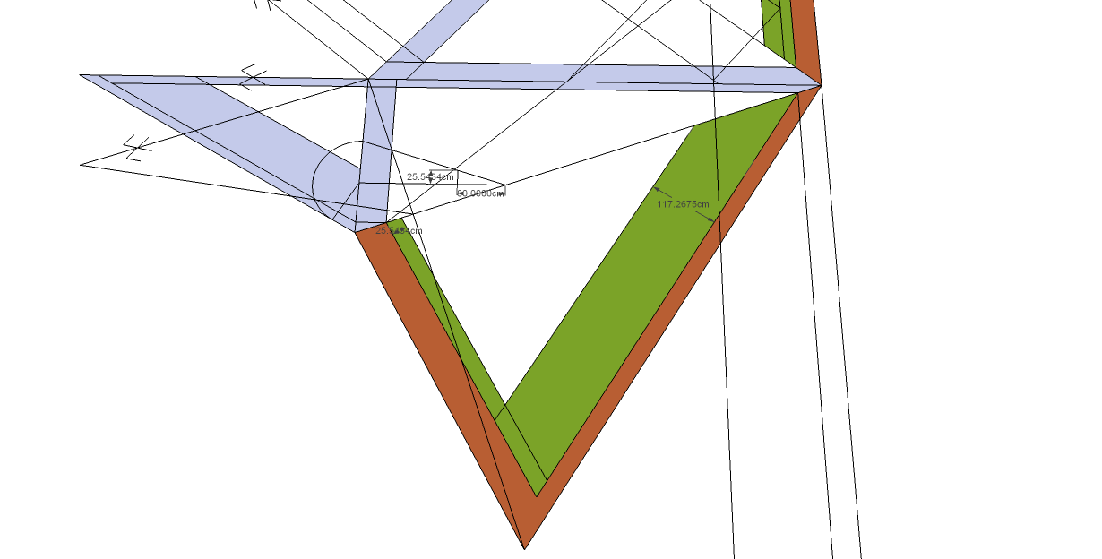
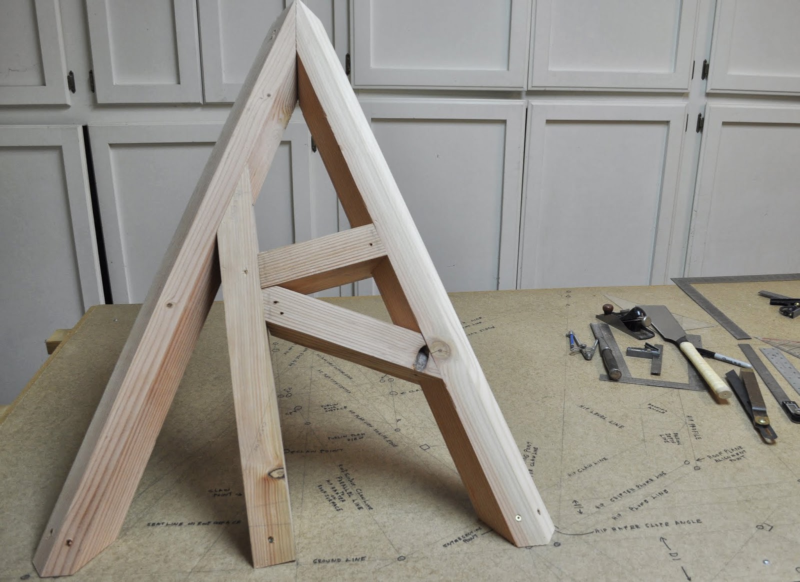
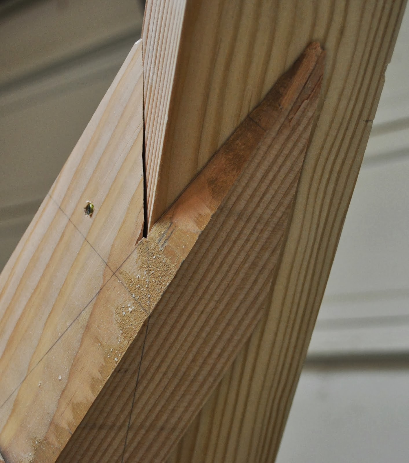
This is a  Swiss designed task model and it's a tough one. Draw out the geometry and build it in 7 hours. Yea, right. The hip rafter on the left side of the task model has a claw on it. I'm just guessing this was the correct development for the hip rafter claw angle. The rotated rafter on the left side of the task model meets the hip rafter at a skewed angle and has a hidden center line that must be transferred to the timber correctly. The cut on the end of this rotated timer is something like the witches cut. Make two different cuts across the timber to produce the correct bevel angles at the foot of the rafter.


Ground Plan. Grundriss


Develop the Profiles for the hip rafters and the dihedral angles as well.

Develop the Jack Rafter Claw Lines.

Develop the internal edge of the hip rafter  and seat line on the folding roof surface.


Mark perpendicular lines on the timber placed over the folding roof surface. Then mark the miter angles, back bevel angles and claw lines.


Both rafters on the right side of the task model marked and developed for the folding roof surface.

Dimension used for the internal edge of the hip rafter on the left side of the task model.


Folding roof surface developed for the left side of the task model.

Profile rafter development for the seat lines in plan view and for the roof surface.


Rotated rafters drawn on the roof surface.


Rotated rafter marked and developed for the folding roof surface.


Drawing for developing the claw lines on the left side of the task model.


The complete geometry for the task model.


Tuesday, November 5, 2013

Der verkantete schräger Giebelsparren

Der verkantete schräger Giebelsparren

  1. The canted oblique gable rafters
  2. Schräger Sparren
  3. Sloping Rafter
  4. Oblique Rafter
  5. Slanted Rafter
  6. Prow Rafter
  7. Crow's Peak Gable Rafter
  8. Crow's Peak Prow Rafter
Whatever you call the prow gable rafter rotated perpendicular to the roof surface it can be challenging, to find the correct miter angle and saw blade bevel angles for the ridge cut.  The article "Framing a Prow Roof(s)" by Scott Wells, published by ThisIsCarpentry.com by Gary Katz, is an excellent article on how Scott Wells solved the problem. 

Prow rafters that are plumb to the earth are easy enough to figure out, but once the prow rafter is rotated perpendicular to the roof surface the ridge cut angles are not that obvious. Scott had to build both types of prow rafters on Gary Katz's new shop and Scott used full scale geometry on a piece of plywood to find the angles for the prow rafter plumb to the earth. He then used SketchUp to draw a 3D model of the prow rafter rotated perpendicular to the roof surface. His SketchUp video is worth watching for all carpenters. The protractor and tape measure tool in SketchUp are a carpenters best friend. Scott also shows you how he used the Angle Between Faces ruby sketchup plugin by Clark Bremer of the Timber Framing Guild to find the dihedral angle at the ridge cut to find the saw blade bevel angle that was used to cut the prow rafter ridge cut.

The math for the prow rafter rotated perpendicular to the roof surface peaked my interest, especially since I've been studying the different ways to draw out the geometry for the rafters for the WorldSkills Carpentry Competition. This first drawing would be the correct geometry to use in the Carpentry Competitions, because you're suppose to cut the prow rafter ridge cut with a handsaw.


If we're using a compound miter saw like Scott, then we'll use some trigonometry to calculate the saw blade bevel angle.

Profile Rafter Slope Angle = 18.43495°

Prow Plan Angle = 71.56505°

Prow Hip Rafter Slope Angle = arctan(tan(18.43495) * sin(71.56505)) = 17.54840°
Miter Angle = arctan(cos(17.54840) ÷  tan(90 -71.56505)) = 70.73022°
Miter Angle American = 90 -  arctan(cos(17.54840) ÷  tan(90 -71.56505)) =19.26977°
Saw Blade Bevel Angle = arccos( cos (Plan Angle ) ÷ cos ( Miter Angle ))
Saw Blade Bevel Angle = arccos( cos ( 71.56505 ) ÷ cos ( 70.73022 )) = 16.62096°

This model was confusing, because the prow hip rafter slope angle was the same as the jack rafter side cut angle. So I used a Tetrahedron Slice to see if I could understand the trigonometric relationships better. No, the tetrahedron slice didn't make it any clearer.  


For WorldSkills Carpentry Competitions we need to draw out the roof using geometry, but for everyday framing practices I think Scott's 3D drawing in SketchUp was the best way to solve the problem of finding the prow rafter miter angle and saw blade bevel angle for the compound cut.


Sunday, November 3, 2013

Draw Down Technique

The Draw Down Technique for task models is a game changer. It's so easy that I could easily teach a first year apprentice to draw out the Draw Down Roof Surface to mark and cut the rafters rotated into the roof surface plane. It's so simple I envision putting the Saint Andrews Cross at the top of the next hip roof we frame. After you have the Draw Down Roof Surface drawn you can easily rotate a rafter in any direction on the roof surface.

In German the Draw Down Technique is called Abklappung . Which translates to Enlightenment or Elucidation. It's absolutely an Elucidation to the drawing and cutting of timbers in the roof surface. Stereotomy, the Art du Trait or Art of Line should/must be studied, but the Draw Down method is a technique that we can use on full size roofs that we frame everyday.

When I first started the task model drawing yesterday, using the Draw Down Technique, with all of the lines right on top of each other I got lost in the thought process and used my H1 dimension for the height of the claw angle where it intersects the hip rafter. My H1 dimension is the plumb height on the hip rafter minus the depth of the hip rafter backing line. It should only be used on rafters that are plumb to the earth, not on rafters that are perpendicular to the roof surface. Then I started to use the hip rafter housing angle dimension from the purlin study and I realized that dimension only worked if you already knew the hip rafter housing angle for the rotated rafter, which I did/do not know. Only a full Devers De Pas drawing would give you the angle, which I did not intend to include in this drawing.


Back to the drawing board.

After drawing out the Draw Down Roof Surface over the plan view of the task model, it became evident that the amount of lines crossing each other were confusing, so I labeled all of the lines on the task model drawing board. Tony and Dan teacher their apprentices to use colored pencils for the different lines on the roof surface, but all of my color pencils have too soft of a lead to make accurate lines on the drawing board. Need to find color pencils with a harder lead.

The second mistake I made on the task model drawing was by not drawing in the seat line on the roof surface for use with the main rotated rafter. Instead I used the plan view seat line to mark off the seat of the rotated rafter and when I put the task model together it was more than obvious the seat cut was wrong. So I had to cut an 1 1/2" off the level cuts of the rafters with my BigFoot Beam Saw. So, the task model doesn't fit the plan view lines in the drawing. Nor is the seat cut perfect on the rotated rafter.

Anyway, the real game changer is how easy it is to mark the miter and claw angles on the timber using the Draw Down method. After you draw out the correct lines for the Draw Down Roof Surface , it's simply a matter of drawing perpendicular lines on both sides of the timer at the location of the seat line, miter line or claw line. No, stereotomic or true shape drawings off to the sides of the roof surface, that easily lend to confusion of which perpendicular lines to use for the true shape of the timber on the roof surface. This happens a lot with roof bevel angles that are greater than 80°. The lines are so close together it's hard to tell which line to use for the true shape of the 3D drawing.

Draw Down Technique drawing steps:

  1. Draw the Plan View of the Hip Rafters
  2. Draw the Profile of the Common Roof Rafter.
  3. Draw the center line edge line of the hip rafter on the roof surface.
  4. Draw the perpendicular lines at the foot  of the profile rafter that establish the dimension for the internal edge of the hip rafter on the roof surface, plan view seat line, roof surface seat line.
  5. Draw the Hip Rafter in Profile to transfer a perpendicular line for the intersection of the hip rafter on the roof surface for the claw lines.
  6. Draw the internal edge of the hip rafter on the roof surface.
  7. Draw the claw lines on the roof surface.
  8. Transfer the rotated rafters from plan view to the roof surface view using perpendicular lines.
  9. Draw out the sides of the rotated roofs in roof surface view using a scrap of lumber the same width as the rotated rafters.
  10. Draw perpendicular lines on the side of the timber placed directly over the roof surface view of the rotated rafter for the seat lines, miter lines and claws lines.
  11. Draw the back bevel lines on the top and bottom of the timber from the perpendicular lines on the sides of the timber.
  12. Cut & assemble the roof rafters.


Here's a couple of drawings showing how I would/could easily add rotated rafters to a Hexagon Roof or a simple hip roof. 


Wednesday, October 30, 2013

European Task Model #2


This European Task model is from Tony McGartland from South West College, Omagh. N.Ireland, who helps train the UK/Ireland apprentice carpenters for the WorldSkills Carpentry Competition. While going thru this geometric exercise I discovered a real easy way to draw out crossing rafters, Saint Andrew's Cross Rafters or any rafters perpendicular to the roof surface like purlin rafters.


Here's the ground plan for the task model with the profile rafter and the heights-locations of the crossing rafters.


Added the hip rafter profile.


This task model is similar to the Schräge Sparren model where the top edge of the hip rafter is beveled in one direction only.

Here I developed the roof surface.


In this next drawing I drew out the backing angle for the hip rafter and I also used the rotated rafter block to determine the dimension of the internal edge of the hip rafter on the real roof surface. Then I drew some perpendicular  lines to the crossing rafter on the roof surface to develop the miter angle of the crossing rafter.

The crossing rafters are 40cm x 40cm. Use a 40cm x 40cm rafter block perpendicular to the hip rafter backing triangle to determine the dimension for the internal edge of the hip rafter on the roof surface that is drawn parallel to the edge of the hip rafter on the roof surface.


This is a 3D drawing of the crossing rafters. When two rafters are perpendicular to the roof surface, the miter angle on the side of the crossing rafters is 90°.


Here I'm checking the miter angle of the crossing jack rafter at the foot of the crossing rafter where it intersects the hip rafter.

Here's a 3D drawing of the two crossing rafters as they intersect at the hip rafter.


Checking the miter angle of the crossing jack rafter at the intersection of the hip rafter.


Drawing of the king common rafter at the intersection of the hip rafters.

3D drawing showing the crossing rafters that are rotated into the roof surface.


These next three drawings are priceless. Over the last 5 months, that I've been studying the Traditional layout techniques, the French & German Traditional Layout Books do not show this technique of placing the lumber over the roof surface drawing and drawing perpendicular lines at the edge of the hip rafter and perpendicular lines at the internal edge of the hip rafter on the roof surface. These  perpendicular lines automatically develop the correct miter and bevel angles for the rotated rafters. No need to draw perpendicular lines off to the side of the roof surface to develop the true shape of the crossing rafter.


Tuesday, October 29, 2013

European Task Model #1

Tony McGartland from South West College, Omagh. N.Ireland, who helps train the UK/Ireland apprentice carpenters for the WorldSkills Carpentry Competition sent me a couple of the European Task Models. These task models look like fun projects. This first task model has the typical irregular hip rafter on an eave angle of 105° with jack rafter with claws. There's also one rafter plumb to the earth and skewed from the plate line.


One thing that's confusing in the task model drawing is the color of the orange - brown rafter on the right side of the drawing. I don't think it should have been the color orange-brown like the hip rafter, because it's just  a rafter that's plumb to the earth and skewed from the plate line. It's a Schräge Sparren and has a top bevel edge, but it's not a hip rafter in this drawing. Hip rafters have a dihedral angle triangle and Schräge Sparren  do not. It's similar to what we call a gable end prow rafter. But the Schräge Sparren top edge is beveled. 


Plan View of the Task Model


Rafter Profiles developed from Plan View and the Jack Rafter Claw Angles developed from the prism plane geometry.

The task model wasn't clear on the tail slope angle, unless you speak Danish, so I used a tail slope angle 105° to develop the Hexenschnitt -- The Witches Cut on the hip rafter and the Schräge Sparren.