www.heartwoodschool.com
In Will's article he explains how to develop the jack rafter tenon on the folding roof surface and goes onto explain how to use the Hawkindale Angles, P2, P5 and A9 for the mortise tenon layout on the hip and jack rafter. I started off using the draw down roof surface method for one of the jack rafters with the square cut tenon. It worked, however I then used the profile rafter to develop the jack rafter with the square cut tenon and thought it was more accurate and easier to layout. Four perpendicular lines from the jack rafter in plan view develop the jack rafter with the square cut tenon in profile view. The one thing I wasn't sure of, was the seat cut on the bottom of the jack rafter or seat housing in the hip rafter mortise. So I used the jack rafter lip-claw angle for the bottom seat angle on the jack rafter with the square cut tenon. Developing the claw line angle using geometry for the jack rafter is pretty straightforward, but you also need to know the depth of the mortise on the hip rafter. The depth of the mortise is taken from the hip rafter profile view.
Update: Will Beemer emailed me saying that the seat on the bottom of the jack rafter uses the clip-lip-claw angle on the bottom of the jack rafter for the housing seat, but the tenon is cut so the tenon has continuous grain.

After laying out the hip rafter in profile, I saw that I could layout the mortise for the tenon on the unbacked shoulder of the hip rafter. The layout on the hip rafter is 90° to the edge of the hip rafter for the square cut tenon and the other angle is the hip rafter side cut angle that we already have from the geometric layout at the foot and peak of the hip rafter. I mortised the hip rafter before I edge beveled the hip rafter for the hip rafter backing angle. With the mortise for the square cut tenon already cut on the hip rafter it automatically develops the correct angles once the hip rafter rafter is backed out. Just like the head cut of the hip rafter. The hip rafter side cut angle develops into the jack rafter side cut angle when the hip rafter is backed out, edge beveled.
You could layout the square cut tenon using a framing square. The angles you would need to know are the jack rafter side cut angle, hip rafter side cut angle, hip rafter and jack rafter slope-pitch. You could use the slope of the roof for the seat on the hip rafter square cut mortise and leave the bottom of the jack rafter without a seat.
This is one of those projects where everything went wrong that could go wrong. I cut the 2x4 base plates only to realize that my compound miter saw blade was not square to the table saw. So all of the cuts on the base plates are not perfect. Then I dry fitted some of the task model pieces with wooden dowels made of poplar, that broke when the pieces were doweled together. Alot of the cuts with my dull japanese pull saw don't look perfect. I started off the project thinking I was going to dowel and glue all pieces. After assembling the base, post, ridge and knee braces with dowel I'll never use dowels again.
Here's a link to the 70 or so photos of the project.
I started off by drawing the task model on a piece of drafting paper 4' x 6' . It was fun, but the eraser and everything else, left too many smug marks and I needed a place to build the task model.


I finally used several sheets of thick poster board to draw out the remaining geometry.

Picture of the geometric layout for the mortise on the unbacked shoulder of the hip rafter.


Hip rafter with mortises cut on the unbacked hip rafter.

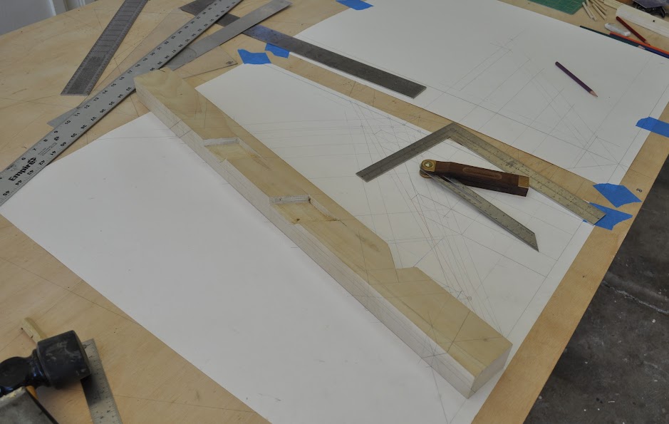
Here I'm checking the depth of the mortise and checking to see if the mortise is square to the edge of the hip rafter.


Jack Rafter square cut tenon geometric layout in profile.


In this drawing I'm laying out the valley rafter. The top of the valley rafter has one edge that is beveled for the valley rafter backing angle and the other top edge is square-flat, not backed out. For the edge that is not backed out the valley jack rafters will have an upper claw that rest on top of the valley rafter.


Drawing showing the square tail cut on the valley rafter.


I started labeling the lines in the drawing. Either claw, bevel or seat to make it easier to lay out the valley jack rafters with claws.


I also labeled each line on the timber with c for claw line, b for back bevel line or s for the seat line.


You can never have enough framing squares.

Picture of the jack rafters with the square cut tenon and the valley jack rafters with the upper claw resting on top of the valley rafter.