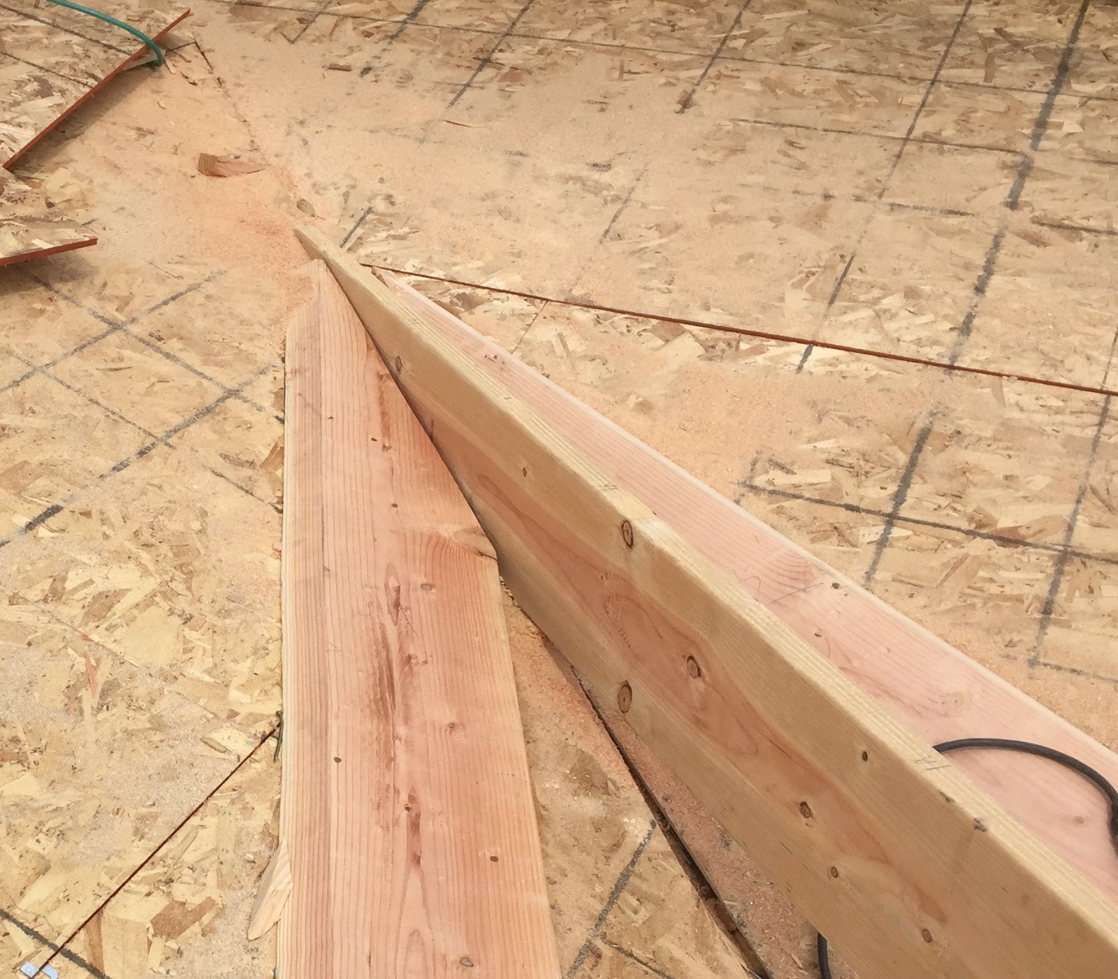
Sunday, October 18, 2015

Ancient Knowledge Tour of Roof Framing Geometry Class


BuildZoom Master Series class on traditional roof framing geometry was taught by Billy Dillon and Sim Ayers at BuildZoom's office in San Francisco California. This class on Traditional roof framing geometry , Art Du Trait - Schiftung, is the geometrical knowledge and techniques used for drawing out complex cuts of solid objects, on 2 dimensional planes on paper or wood drawing boards. It's a simplified technique developed from the ancient art of stereotomy. You can use trigonometry to layout a lot of compound joinery, but transferring lines from a drawing board makes makes a lot of the  compound joinery quite simple.

One of the questions that came up before the class began was, what books to buy on traditional roof framing geometry for carpenters wanting to learn Art Du Trait - Schiftung, that's in English. Our answer, none. It's definitely something that needs to be addressed. There's plenty of advanced books in French and German on this subject, but there are no books written in English that explain the theories of laying down the lines on paper for developing complex cuts on a 2 dimensional plane for beginners.

Billy and I decided the easiest way to teach  someone traditional roof framing geometry was to start with the roof framing kernel. It's not the geometrical drawing technique used for  Art Du Trait - Schiftung, but it's an easy way for American carpenters to comprehend the laying down of planes in a one day class. The main difference between the  roof framing kernel and Art Du Trait - Schiftung, is that the roof framing kernel does not use a depth or width for the profile rafters. 

Billy drawing out the geometry for the roof framing kernel. With the roof framing kernel you can use the grasshopper method, bevel square, to transfer angles from the drawing to the timber.

The roof framing kernel folded out  with the real roof surfaces developed and the technique used to draw out the hip rafter backing angle. Everyone in class draw out the kernel and then cut and folded the roof framing kernel drawing to have a better understanding of folding planes.
Everyone trying to draw out the hip rafter backing angle as well. I was quite impressed with some of the student drawings. I checked Tim's hip rafter backing angle on his drawing and it was right on the money.


Billy drawing out the geometry for Dachausmittlung, Geometric Roof Design, roof averaging. This drawing technique is used to locate the hip run lines on complex roofs that don't have eave lines meeting at a 90°.


After lunch Billy draw out some of the geometry for the eyebrow roof dormer. 


Billy explaining the direction of the edge bevel of the elliptical valley rafter to Brian Copper.


After lunch I explained the hip rafter plumb line shift for the edge bevel on the hip rafter. Developed from the intersection of the level plane line and the hip rafter plumb line shift.  Jason Smith then used his draw knife   and hand plane to edge bevel the hip rafter in this picture. 


We moved on pretty fast after lunch. We were all pretty much burnt out from the morning geometry session .  Or at least I was. The morning session went really well for the amount of information that the students were presented with.  After explaining how to draw out the TE (top edge) and BE (bottom edge) of the rafters on the fold down roof surface, I had all of the students lay a block of wood on the folded down roof surface drawing board and transfer the miter and bevel lines to the purlin rafters. In this picture Greg is cutting his purlin rafter with Jason and Eric installing the purlin rafter Eric cut, with Scott looking on.


Tucker transferring the lines on the fold down roof surface to the purlin rafter with Scott cutting his purlin rafter.


Here's a picture of Jason at my house on Friday transferring the lines from the fold down roof surface to the purlin rafter.


Everyone in the class cut a purlin rafter from the fold down roof surface drawing. Jason and Eric cut the timbers for the Saint Andrews cross on the right side of this Octagonal  task model.

Many thanks to Andrew Fischer at BuildZoom for putting the Master Series class together.


Sunday, September 13, 2015

Off Angle California Valley Framing

Off Angle California Valley Rafters can be calculated using one of my RafterTools+ apps.


On this house the main roof slope is an 4:12 pitch and the off angle California framing is at an 6:12 pitch. First enter 4:12 for both the Main and Adjacent Roof Pitches, with an Eave Angle of 90°. The calculated results will give you the Main Roof Hip Rafter Slope Angle = 13.26268° and the  Main Roof Hip Rafter Back Angle = 12.92097°. 

To calculate the California Jack Rafter Foot Miter Angle and Saw Blade Bevel  Angle for the Off Angle California Valley Framing  can be accomplished by entering an Eave Angle of 45°, Main Roof Slope Angle = 18.43495° (4:12) and Adjacent Roof Slope Angle = 26.56505° (6:12)


Roof Eave Angle = 45°
Main Roof Slope Angle = 18.43495° (4:12)
California Valley Roof Slope Angle = 26.56505° (6:12)

Main Roof Hip Rafter Slope Angle = 13.26268°
Main Roof Hip Rafter Back Angle = 12.92097°

With the RafterTools+  calculated results you get an 

Valley Sleeper Saw Blade Bevel Angle = 48.46304°


For the Jack Rafter Foot  Miter Angle you add the California Valley Roof Slope + Main Roof Hip Rafter Slope Angle.

Jack Rafter Foot  Miter Angle = California Valley Roof Slope + Main Roof Hip Rafter Slope Angle
Jack Rafter Foot Miter Angle = 26.56505 + 13.26268 = 39.82775°

For the Saw Blade Bevel Angle used on the Jack Rafter Foot Cut

Saw Blade Bevel Angle at Jack Rafter Foot Miter Cut = Main Roof Hip Rafter Backing Angle
Saw Blade Bevel Angle at Jack Rafter Foot Miter Cut = 12.92097°

 The  RafterTools+ has the California Jack Rafter Length Difference  or use the following Trigonometry formulas.

Roof Sheathing Angle = arctan(sin(Jack Rafter Foot  Miter Angle) ÷ tan(Main Roof Hip Rafter Back Angle)
Roof Sheathing Angle = arctan(sin(39.82775) ÷ tan(12.92097) = 70.29288°

California Jack Rafter Length Difference = O.C. Spacing ÷ tan(Roof Sheathing Angle)
California Jack Rafter Length Difference = 24” ÷ tan(70.29288) = 8 5/8"


The Valley Sleeper Miter Angle is not built into the RafterTools+ apps. You can use the following formula for the miter angle at the foot of the Valley Sleeper.

Valley Sleeper Miter Angle = arccos( cos(Sheathing Angle Angle) × cos(Jack Rafter Miter Angle at Foot))
Valley Sleeper Miter Angle = arccos( cos(70.29286°) × cos(39.82772°)) = 74.99102°

With a Valley Sleeper Saw Blade Bevel Angle of 48.46304°, you can use this formula for the snap line dimension on the Valley Sleeper for the edge bevel.

Edge bevel width = Valley Sleeper Thickness / tan(Valley Sleeper Saw Blade Bevel Angle)
1.69323 = 1.5 x tan(48.46304°)
or 1 11/16" = 1.5 x tan(48.46304°)


Set the saw bevel angle to 48.46304° for the Valley Sleeper edge bevel.


After you have edge beveled the valley sleeper you can use the Valley Sleeper Miter Angle (74.99102°) for the Valley Sleeper foot cut.


This porch has trusses and I aligned the valley sleeper with the edge of the truss for the location of the valley sleeper.


The ridge cut has a 4:17 miter angle to set on top of the main roof valley rafter. I scribed the miter angle for the valley sleepers at the peak. 


For the Off Angle California Valley Jack Rafters I laid out the 6:12 level cut, then used the 39.82 angle for the Jack Rafter Foot Miter Angle.


For the Off Angle California Valley Jack Rafters length difference I used the 8 5/8"  from the RafterTools+app.


The extra blocks at the ridge are for a CS14 strap that runs the full length of the roof. The second row of blocks are for plywood sheathing edge nailing.


Saturday, July 25, 2015

Ancient Knowledge Tour


Ancient Knowledge Tour of Roof Framing Geometry

Sim Ayers & Billy Dillon

Saturday Oct. 17
San Francisco, California

The class has been moved to BuildZoom's office in  San Francisco


501 Folsom St, San Francisco, CA 94105,
8:00am to 5:00pm
Registration cost is $100.00


Sponsored by BuildZoom BuildZoom


Co-Sponsors
Simpson Strong Tie
JLC Magazine -- The Journal of Light Construction -- Hanley Wood Company
WindsorOne -- Protected Trim


This will be a hands on workshop/class on advanced roof framing. 
Cut complex roofs like the master carpenters of Europe.

Tools required for the class:

12”compass 
2-45º drafting triangles
1-30º - 60° drafting triangle
straight edge
scissors
framing square (no rafter tables needed)
drafting protractor
drafting pencils
colored drawing pencils
eraser
Japanese Pull Saw (handsaw)

Optional Tools for the class, if time allows for Hip Rafter Edge Bevel:

Draw Knife
Hand Plane

Topics covered in the workshop:

Roof Framing Kernel , with fold out and fold down roof surface planes
Rule of Thales, converting degrees to radians i.e. 57.3
Eyebrow Dormers, Groin Vaults, Curved Hip Rafters  using ordinates
Scribing timbers using a French plumb bob
Transfer angles and lines to the stick (timber), grasshopper method.
DoppleShifter

Ad Quadratum -- Octagonal Roof Framing
Plumb To the Earth
Trait Car -- Perpendicular

Ad Triangulum
Hexagonal Roof Framing
Layover Valley Rafter
Curved Rafters

Schiftungen
Dachausmittlung
'L'Art du Trait'
Roof Framing 
Geometry

Schräge Sparren 
Canted Rafters
French Devers de pas drawing technique
German Shadow Line drawing technique

Treteaux Angles
Rotated Hip Rafters
Roof Axis Plane
Pentagonal Roof Framing

Backenschmiege
Abgratungswinkel
Hip Rafter
Backing Angle
Edge Bevel
Basic Shift

Klauenschifter
Rafter Claw -- Barbe Angles
Eyebrow Dormers

Hexenschnitt
The Witches Cut
Square Tail Fascia Angles


Besides the roof framing geometry, if time allows, for Simpson Strong Tie --- We'll show you how to install HDU hold downs correctly and how to nail plywood shear wall plywood correctly, when the On Center spacing is 2" O.C.


Sunday, July 12, 2015

Curved Hip Rafters


I came across this method of drawing out the curves of hip rafters in a Carpentry & Building magazine published in 1880 and thought it was pretty easy way to establish the curve of any hip rafter using this method. It can be used for the curved hip rafters on flared radius eave rafters, curved hip rafters on bay windows or a hip rafters with any eave angle.

To use this method draw the elevation view of the common rafter and hip rafter above the plan view of the radius rafters. Draw the radius/ Arc of the common rafter. Then draw equal spaced horizontal lines that intersect with the hip rafter slope line in elevation view. Drop some perpendicular line where the horizontal lines intersect the hip rafter slope line and the common rafter slope line . Then draw rectangular boxes to establish the cure of the hip rafter based off the curve of the common radius rafter.


Geometric drawing of the curve of a standard hip rafter and Octagon hip rafter  with a common radius rafter. 


Drawing for the curve of the bay window hip rafter and the curve of the hip rafter against the wall of a bay window.

Section of a Bay window in Plan View

How to draw out the arc of the common radius rafter on a bay window.


Geometric drawing of the curve of bay window hip rafter and the curve of the hip rafter against the wall of a bay window using the rectangular boxes to establish the curves of the rafters.


Wednesday, March 25, 2015

French Timber Framing

Some really good examples of French Timber Framing can be seen on Piedefer Olivier facebook page.  These are just some of the pictures from Piedefer's facebook post. It's great when we can see the  French timber framing we're studying from books. Especially the use of the principal rafter, knee braces, purlins with batten rafters. He uses a lot of old used timbers and some of the mortise and tenon in the twisted timbers are a good study on scribing. The saint andrews cross's at some of the ridges is also interesting, but then there's the timber framed gable walls as well with mortise and tenon in the twisted gable stud timbers.

If you're interested in Timber Framing  click on the link below to visit Piedefer Olivier facebook page. (I'm not sure what photos are public)

Piedefer Olivier


Saturday, March 14, 2015

How to draw a Pentagon

I was researching the easiest way to draw a pentagon with one side known. I think this method based on Euclid Elements book 6 proposition 30 is the easiest to remember. Which is how to cut a line into a long part and a short part medially. It's basically the problem of dividing a line segment into two unequal parts, such that the whole is to the long part as the long is to the short. That doesn't make a lot of sense until you draw the pentagon using the  golden ratio  of 1.61803398875.

Golden Ratio Formula


Basically all we need to remember is the number  1.618

With one side of the pentagon known, 292mm in this example. The long part of the whole is equal to 1.618 x 292 = 472.456.

Step 1:
Draw a line equal to the known side length. Then draw a perpendicular bisector.

Step 2:
Draw two arcs from center point A & B using radius 472.456.


 Step 3:
Draw two lines intersecting the perpendicular bisector where the arcs intersect.


Step 4:
Draw two arcs from center point A & C using radius 292.


Step 5:
Draw the lines that form the pentagon.


Step 6:
Draw perpendicular bisectors on each side of the pentagon for the profile rafter runs.


Step 7:
Draw the hip rafter run lines, radius lines of the pentagon.