Sunday, March 20, 2016

Guitarde Dormers Carpenter's Art


French Guitarde
Wall dormer or Balcony, circular or elliptical in plan view

This drawing is of two intersecting cylinders. I think I can develop the orthographic projections that will develop the correct curve of the intersecting cylinders.  I need to study this a lot more.


I started off with these two intersecting cylinders and realized that the horizontal cylinder is not rotated correctly. 

The horizontal cylinder rotated correctly for the guitarde.

 I'm not sure, but you might be able to build a guitarde with a cylinder and sloping plane. However, most of the guitardes look like the intersection of cylinders or cones.

Comparison of the sloping plane and horizontal cylinders intersecting the vertical cylinder.


Orthographic development for the sloping plane for a circular plan. 


Here are links to pages on the internet with the guitarde images on this page.


By Odeee (Own work) [CC BY-SA 3.0], via Wikimedia Commons


http://www.historicalcarpentry.com/guitarde---beautiful-french-dormers.html

http://www.historicalcarpentry.com/master-piece-photos.html

http://manoirs-cauchois.blogspot.com/2012_09_01_archive.html

http://www.lecompagnonnage.com/?Brive

http://compagnonnage.info/blog/blogs/blog1.php/2012/02/08/une-belle-guitarde-a-vendome-41

http://creationsculturejeuxdemeuzac.blogspot.com/2013_01_01_archive.html

http://imagesdouvrages.free.fr/compagnonnage_guitardes.htm


https://www.google.com/search?q=guitarde+french+dormer&newwindow=1&espv=2&biw=1920&bih=955&tbm=isch&tbo=u&source=univ&sa=X&ved=0ahUKEwimwMbCqKrLAhVGzGMKHb3GA8AQ7AkILg#newwindow=1&tbm=isch&q=guitarde++Compagnonnique&imgrc=dFTydk5a9hQ_bM%3A

Sunday, February 21, 2016

Octagon Overlay Sleeper Math Notes

I thought I could break down the different parts to an Octagonal roof overlay, so you would only need to use some trigonometry to calculate the different dimensions to precisely frame the Octagonal Roof Overlay, California sleepers. However, I don't think it's possible. To precisely locate the sleepers on the main roof you have to geometrically draw out the main roof surface showing the location of the valleys sleepers developed from the location of the valleys sleeper in plan view.


In this drawing I developed the roof surface of the Octagonal Roof from the Octagon roof in plan view and elevation view. You can developed the valley sleepers on the octagonal roof surfaces, but it does not give the location of the sleepers on the main roof surface.


 To develop the Octagonal Roof sleepers on the main roof surface you need to rotate the Octagon in plan view, so it's perpendicular to the main roof slope in the Octagon in elevation view. Dropping perpendicular from the main roof slope in elevation view develops the location of the sleepers on the main roof surface.


After you've developed  the sleepers on the main roof surface when you can get the sleeper miter angles you still need a saw blade bevel angle to miter the two sleepers together. You can use this formula for sleeper #1, Saw Blade Bevel Angle = arcsin(sin main roof slope) x cos(67.5)). For the saw blade bevel angle for the miter at sleepers #2 & #3 use  Saw Blade Bevel Angle = arcsin(sin main roof slope) x cos(22.5)). Or you can use the RafterTools+ app on the iPhone. Enter 135° eave angle and use the hip rafter backing angle for the Saw Blade Bevel Angle. Use an eave angle of 45° for the saw blade bevel angle for sleepers #2 & #3.

Use the same saw blade bevel angle to cut the miter on the bottom of the Octagonal Hip Rafters that frame into the sleepers. For the miter angle cut at the hip rafters that frame into the sleeper you could also use Layover Cut Angle = Layover Rafter Slope Angle + arctan (tan Main Roof Slope Angle x sin Layover Rotation Angle in Plan View) ....where the Rotation Angle in Plan View is  67.5° and 22.5°.

Sunday, January 10, 2016

45 Plan Angle Rake Wall Plates


Yesterday, I was building the rake walls for a corner fire place. I have studied rake wall plates rotated into the roof surface plane quite extensively. However, yesterday I just couldn't remember how to calculate the rake plate miter angles. So this post is a reference for me the next time I'm on the jobsite building rake walls rotated into the roof surface plane.


Here's a drawing of the corner fire place I was building. The roof slope angle was 26.56505°, 6:12, with a 135° eave angle for the wall rake plate rotated into the roof surface.


Saw Miter Angle for Common Rafter Pitch Rake Wall = arctan ( tan (Direction Of Saw Travel ) ÷ cos (Roof Slope ))

R2 = Saw Miter Angle for Common Rafter Pitch Rake Wall = arctan ( tan (22.5° ) ÷ cos (26.56505° )) = 24.84908°

R2 = Saw Blade Bevel Angle = arcsin ( sin (26.56505° ) × cos (22.5° )) = 24.40422°

Saw Miter Angle = 180° - Real Roof Surface Angle - Saw Miter Angle for Common Rafter Pitch Rake Wall
H2 = Saw Miter Angle = 180° - 138.18969 - 24.84908= 16.96123°
H2 = Saw Blade Bevel Angle = arcsin ( sin (26.56505° ) × cos (22.5° )) = 24.40422°


A1 = Saw Miter Angle = arctan ( cos (26.56° ) ÷ tan (67.5° )) = 20.32886°

A1 = Saw Blade Bevel Angle = arcsin ( sin (26.56° ) × cos (22.5° )) = 24.3996°


Saw Miter Angle = 180° - Real Roof Surface Angle - Saw Miter Angle for Common Rafter Pitch Rake Wall

H1 = Saw Miter Angle = 180° - 131.81031 - 20.32886= 27.86083°

H1 = Saw Blade Bevel Angle = arcsin ( sin (26.56° ) × cos (67.5° )) = 9.85418° 


Hip Rake Wall Studs
Hip Rafter Pitch Angle = arctan( tan( Pitch Angle ) * sin( Plan Angle ))
Hip Rafter Backing Angle = arctan( sin( Hip Rafter Pitch Angle) ÷ tan( Plan Angle ) ) 
Hip Rafter Plumb Backing Angle = arctan( tan( Pitch Angle ) * cos( Plan Angle ))

Hip Rake Wall Pitch Angle = arctan( tan( Rafter Pitch Angle ) * sin( Working Angle ))
Hip Rake Wall Pitch Angle = arctan( tan( 26.56505.69 ) * sin( 45 )) = 19.47121°
Rake Stud Saw Miter Angle = Hip Rafter Plumb Backing Angle = 19.47121°
Rake Stud Saw Blade Bevel Angle = arctan(cos(Hip Rafter Plumb Backing Angle)* tan(Hip Rafter Pitch Angle))
Rake Stud Saw Blade Bevel Angle = arctan(cos(19.47121)* tan(19.47121)) = 18.4349°


Saturday, January 2, 2016

Divers Hip Rafter Boucher

This method of drawing out the divers hip rafter was shown to me by Olivier Phojo. He said the French compagnon-Professor J.D. Boucher (1890?), developed it. This method of drawing out the diverse hip rafter using the Sauterlle method, bevel square, is brilliant. Boucher may have developed the method, but Olivier drew it out were I could easily understand it. I looked through Boucher's book , L'art Du Trait of Charpente, yesterday and I couldn't find this method in his book.


This method of drawing out the bevel square angles for the divers hip rafter only takes a couple of minutes. 5 minutes at most. It's something Billy and I should teach in our roof framing geometry classes.  


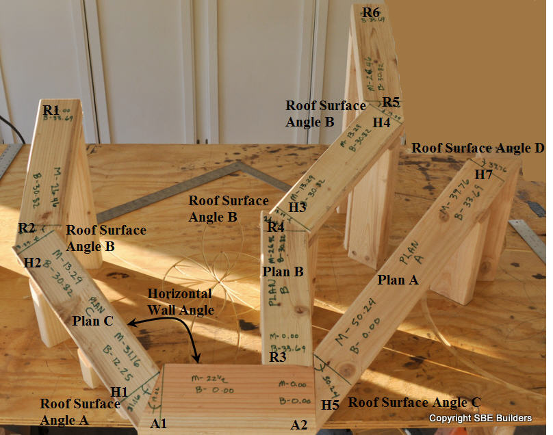
Start off by drawing 2 perpendicular lines. You can draw this on a piece of paper 24" x 18". Then place the framing square on the vertical line and the end point of the framing square on the horizontal line. Trace the framing square for the profile rafter roof slope angle. In this task model I use and 8:12 pitch (33.69007°).


Next draw a perpendicular line to the roof slope line. This line will represent the eave line. I used 12" in this task model for an equal pitched roof. Then connect the eave line to the rise of the roof slope triangle. This line will represent the hip rafter on the roof surface.


At the intersection of the hip rafter on the roof surface with the horizontal line draw a perpendicular line equal in length to the roof slope triangle's tangent. 6 21/32", or 6 11/16" in this task model.


Then draw the diverse hip rafter bevel square lines connecting back to the roof surface triangle.


The red angle is used for the miter angle on the side of the diverse hip rafter. The blue angle is the top bevel on the diverse hip rafter.

The orange angle is used for the miter angle on the side of the diverse hip rafter and the blue angle is used for the bevel angle on top of the divers hip rafter for the first face cut at the head of the divers hip rafter. For the second face cut use the brown angle on top of the diverse hip rafter and the miter angle on the side of the hip rafter will be 90°.


Another drawing using a different roof slope angle. The DP line is easier to understand in this drawing. You don't need to draw the DP line, but you can check your cuts with the DP line.


Here's a picture of laying out the miter and bevel angle on the foot of the hip rafter using the red and blue angles. The cut will be a parallelogram, so you use the same angles on the top and bottom of the foot cut.


Here's a picture of the layout for first face cut at the head of the rafter.


Bottom view of the rafter layout.


The cut at the foot of the hip rafter is complete and the first face cut is complete.


Checking to make sure the foot cut aligns wit the eave line and DP line in elevation view.


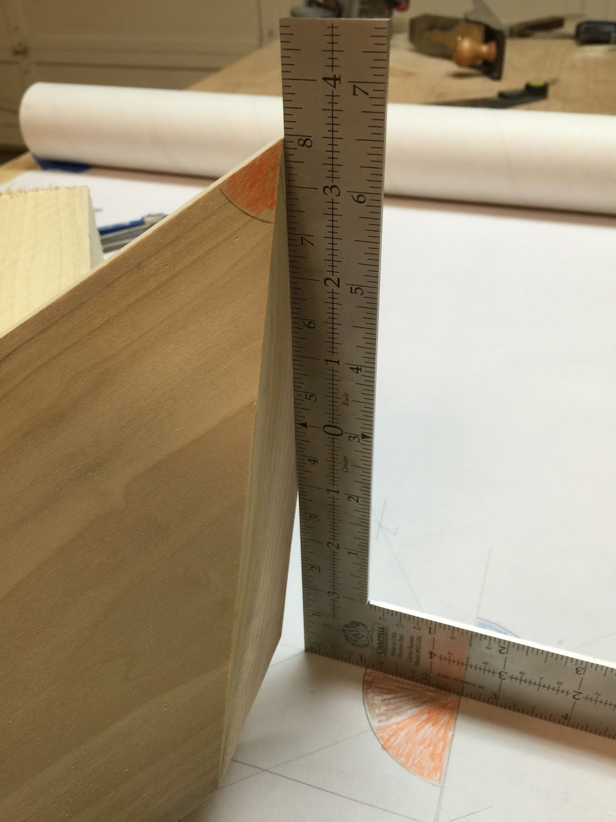
Checking to make sure the first face cut is plumb to the horizontal plane.


For the second face cut you use the brown angle or 90° to the first bevel cut on top of the rafter.


Second face cut laid out.


I checked the accuracy of my drawing using a digital bevel square.


I then used a skill saw for all of the cuts. You could align the blade for the saw blade bevel angles on the timber, but using some math makes somewhat easier.

For the divers hip rafter foot cut I used.
Miter Angle 27.1°
Saw Blade Bevel Angle  = arctan(sin(27.1) ÷ tan(50.24) = 20.7 °

For the divers hip rafter face cut #1  I used.
Miter Angle 49.07°
Saw Blade Bevel Angle  = arctan(sin(49.07) ÷ tan(50.24) = 32.1 °


For the divers hip rafter face cut #2  I used.
Miter Angle 90°
Saw Blade Bevel Angle  = 39.7 °

Here's a link to a PDF file that you can print out for this task model layout.
Boucher 8:12 Pitch


Here's a wire frame drawing of the Boucher technique. Your folding the canted plane flat to the plumb plane of the hip rafter. I'm guessing you can use this same technique for just about any canted rafter.


Another example of folding the purlin rafter (frieze block, bird's block) plane flat. Pretty easy, only 3 triangles.