Friday, April 25, 2014

Roof Framing Geometry Propositions – Axioms

I should have called this article "The Mazerolle Code", because I feel like I'm cracking the secret code hidden in the French book "Traité Théorique et Pratique de Charpente" by Louis Mazerolle published in 1850. Over the last couple of months Joe Bartok and I have looked at Dever De Pas from both sides of the drawing using geometry and trigonometry that define the parallelogram planes in timbers used to develop the upper and lower claw angles.  We also don't think in terms of miter angles on the sides of rafters anymore. It's either an upper claw angle, aka miter angle, or lower claw angles, aka lip angles.

English speaking carpenters are handicapped right from the start when studying Roof Framing Geometry, because we reference roof framing angles using a framing square. To understand the secret code of Roof Framing Geometry that was developed in the 13th century or earlier by the European carpenters you have to think in terms of angles on the stick... Or angles on the timers. As an example  an 8:12 pitched roof  has a slope angle of 33.69007°, but to develop the geometry layout used on the stick, timber, you have to think in terms of 90° - 33.69007°.

In this article we'll try to cover the Roof Framing Propositions – Axioms that define all claw angles for rafters that are plumb to the earth, rotated into the roof surface plane, rotated in any plane or skewed from the plate line.

Roof Framing Geometry Proposition – Axioms  # 1:
All rafters have a DP Line, Devers De Pas Line. The DP line is the line in plan view that follows the vertical plane tilt of the rafter. The DP line can also be the rafter run line for rafters that are plumb to the earth. that have vertical plane tilt of zero degrees. For all rafters that are plumb to the earth, the DP Line is the same as the rafter run line.

Roof Framing Geometry Proposition – Axioms  # 2:
All rafters have a vertical plane tilt line. The vertical plane tilt of the rafter can be zero, like a plumb hip rafter or a plumb common rafter. All purlin rafters will have a vertical plane tilt greater than zero.

Roof Framing Geometry Proposition – Axioms  # 3:
The intersection of the DP Lines of two rafters define the line for the upper claw angle on the rafter.

Roof Framing Geometry Proposition – Axioms  # 4:
The intersection of the rafter DP Line and the hip rafter foot print line define the line for the lower claw angle on the rafter.

Roof Framing Geometry Proposition – Axioms  # 5:
The intersection of the rafter run line and the hip rafter claw line defines the line for the secret line that is used for the lower claw angle on the rafter.

Roof Framing Geometry Proposition – Axioms  # 6:
The secret line is perpendicular to the DP line of the rafter.

Roof Framing Geometry Proposition – Axioms # 7:
A line from the intersection of the DP lines of two Hip Rafters, "a", to the hip rafter slope line "b" following the DP line, with a length equal to an arc length of the side face of the hip rafter lower claw length will determine point "c", for the angle on the bottom of the rotated hip rafter.

Roof Framing Geometry Proposition – Axioms # 8:
The intersection of the Rafter Run Line & TC Line locates Hip Rafter DP Line.

Roof Framing Geometry Proposition – Axioms # 9:
If the hip rafter foot print line is parallel to the jack rafter run line, then the lower claw line for the jack rafter is parallel to the jack rafter run line.

Roof Framing Geometry Proposition – Axioms # 10:
The intersections of the valley rafter roof surface line, at the foot of the valley rafter, and the profile rafter foot print line defines the valley rafter claw line for the upper claw lines on jack rafters.

Roof Framing Geometry Proposition – Axioms # 11:
The intersections of the valley rafter foot print line and the top of the purlin rafter top edge plane line defines the valley rafter claw line for the lower claw line on purlin rafters.

Here's a couple of drawings showing the DP line of a standard purlin rafter and the upper and lower claw angles developed from the Roof Framing Geometry Proposition – Axioms .


Here's a drawing showing the Roof Framing Geometry Proposition – Axioms on a standard roof. Where the hip rafter is plumb and the jack rafter is also plumb to the earth.


Drawing with axioms for a rotated hip rafter and a jack rafter that is plumb to the earth. For jack rafters that are plumb to the earth the vertical plane tilt is always equal to zero and the jack rafter run line is also the DP line of the jack rafter.


Here's a couple of drawing showing how the Axioms work with Joe Bartok's Warlock Rhombic study. The Warlock Rhombic study has two hip rafters square in cross section, rotated 45° to the hip rafter plane and one hip rafter that's has a parallelogram cross section, 60°x 120° rotated 45° to the hip rafter plane. These drawings show the axioms that develop the upper and lower claw angles on both sides of the  parallelogram cross section hip rafter.


There's more Roof Framing Geometry Proposition – Axioms to come...develop.....

Thursday, April 24, 2014

California Valley Sleeper

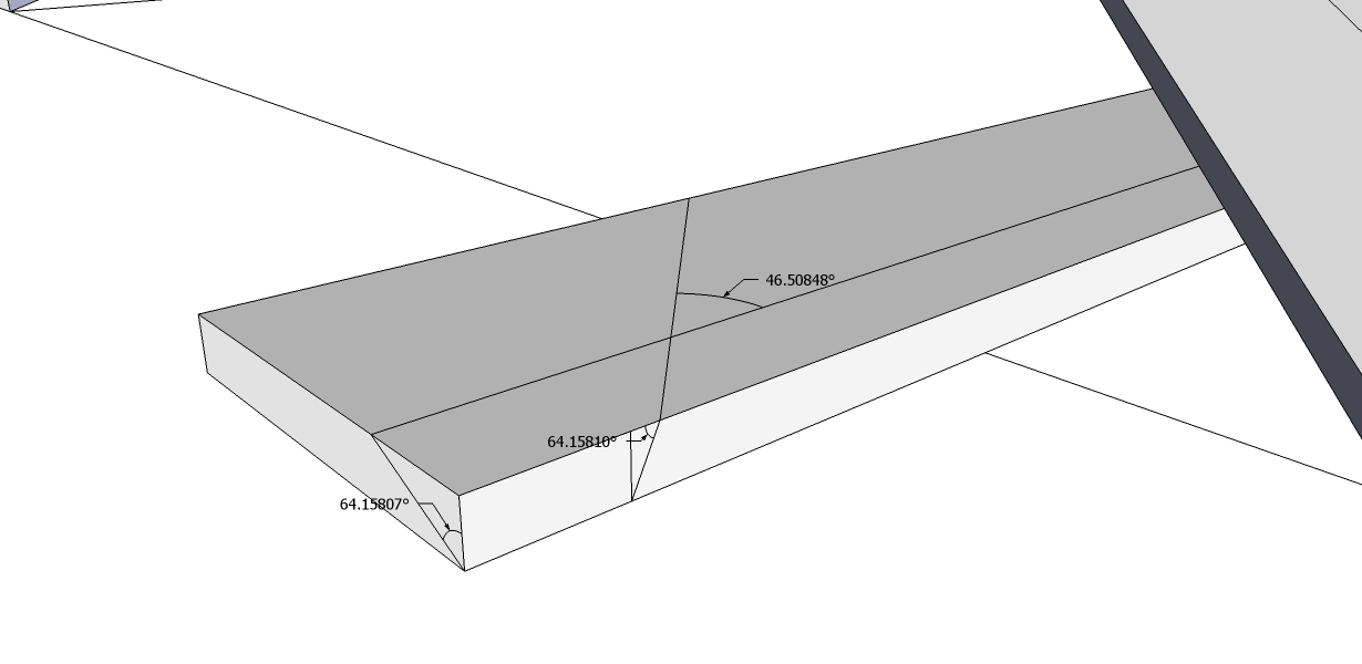
I have California Valley Sleeper's, layover rafters, to install next week and I was trying to see what angles I would use to layout the bevel cut on the foot of the California Valley Sleeper. I've cut a couple hundred valley sleepers and never really thought much about the cut at the foot of the valley sleeper. Mark off the roof sheathing angle at the foot of the valley sleeper and set the saw blade bevel angle to the slope of the roof. After developing a couple of drawings, the correct bevel on the side of the valley sleeper material is the valley sleeper saw blade bevel angle. The compound miter cut on the foot of the valley sleeper results in 90° - Valley Sleeper Saw Blade Bevel Angle.

Also, this is the first time I've seen the call out on the structural roof framing plans for 2x beveled sleepers. Normally, it's just called out as a 2x sleeper.

Valley Sleeper Saw Blade Bevel Angle = 90° - (Main Hip Rafter Backing Angle + Adjacent Hip Rafter Backing Angle)

On this roof it's an equal pitched roof, 4:12.

Roof Eave Angle = 90.00000
SS = Main Rafter Slope Angle = 18.43495
S = Adjacent Rafter Slope Angle = 18.43495
DD = Main Plan Angle = 45.00000
D = Adjacent Plan Angle = 45.00000
R1 = Hip Rafter Slope Angle = 13.26268
C5m Main Hip Rafter Backing Angle = 12.92097
C5a Adjacent Hip Rafter Backing Angle = 12.92097
Valley Sleeper Saw Blade Bevel Angle = 90° - (C5m + C5a) = 64.15807
P2m = Main Jack Rafter Side Cut Angle = 43.49152
90° - P2m = Main Roof Sheathing Angle = 46.50848
P2a = Adjacent Jack Rafter Side Cut Angle = 43.49152
90° - P2a = Adjacent Roof Sheathing Angle = 46.50848


The California Valley Sleeper rotated into the hip rafter position is the same as the trèteau à devers hip rafter. Where the hip rafter is rotated into the roof surface of the roof.

Wire frame sketch of the roof the California Valley Sleeper is rotated into. The rafter slope angles are 90° - rafter slope angle when it's a valley rafter. The other rafter slope angle is the plan angle. 45.00° in this equal pitched roof. The plan angles are the level and miter angles for the equal pitched roof.

The foot of the trèteau à devers hip rafter is the same as the California Valley Sleeper. The head cut miter angle for the hip rafter is also the same as the California Valley Sleeper.

2011 London Dormer #4

Testing the secret line theories on the 2011 London Dormer task model. It works correctly, but would require a 10' x 10' drawing board.

The secret line defines the lower claw angles on rotated purlin rafters. This line is the "Intersection of the Purlin Rafter Run Line & Hip Rafter Claw Line". Drawing a perpendicular from the Secret Line defines the intersection point on the profile drawing of the rotated purlin rafter for the lower claw angle on the rotated purlin rafter. The upper claw angle is defined by the intersection of the hip rafter run line and the DP line.


Tuesday, April 22, 2014

When Hips Collide #3

Drawings showing the secret line. I'm calling it a secret line, because it took me a month to find it. This secret line defines the lower claw angles on rotated hip rafters. This line is the "Intersection of the Hip Rafter Run Line & Hip Rafter Claw Line". Drawing a perpendicular from the DP Line defines the intersection point on the profile drawing of the rotated hip rafter. Drawing a line from the intersection of the plan view DP Lines to the intersection point  draws the line representing the lower claw angle on the rotated hip rafter.


Drawing showing the plane that defines the lower claw angle on the rotated hip rafter.


Drawing showing the hip rafter head cut unfolded. It also shows the 2 parallelogram planes that represent the head cut on the hip rafter.  To layout the head cut on the timber you need 4 different angles and 1 dimension. The 2 upper claw angles that form one of the parallelogram cutting planes and the 2 lower claw angles of the rotated hip rafter that form the other parallelogram cutting plane. It's important to remember that the cutting planes are always  parallelograms. Once you layout 2 of the angles of the parallelogram then the other 2 sides of the parallelogram are automatically developed by using the same 2 angles.


Drawing showing  the geometry for the 2 upper claw angles and the 2 lower claw angles.
Drawing showing the intersection of the DP Lines.


Saturday, April 19, 2014

Hip rafters twisted into the roof surface

Robert Simpson sent me an email with a picture of a drawing of a lectern in Sevilla, Spain. Just about every medieval cathedral has an Octagonal baptismal  and the base of the lectern is Octagonal with the legs of the lectern rotated into the roof surface. Or as Robert stated... twisted into the roof surface. This lectern  looks like some of the bases holding up the masterpieces of the European Trade Guilds dating back to the 13th century.

Possible base of an masterpiece with Saint Andrew's Cross.


Email from Robert Simpson
_____________________________________________________________


Sim,
Earlier this month we were in Sevilla, Spain. In the massive cathedral there was a lectern under repair. Its name in Spanish is Facistol del Coro.You could not see it as it was protected by boards, but on the boards was some explanation, including this illustration.You can see in photo Rafters 1 that the lectern consists of a heavy base, a wooden support structure and a decorative cover with a cupola. Photo Rafters 2 show the support structure a bit bigger, and what do we see?  Hip rafters twisted into the "roof" surface . . .

Recently the construction St Andrew's Cross has come up a lot in your blog.
In the third photo I thought you might like to see its gruesome origins (by Juan de las Roelas, in Fine Art Museum, Seville). de las Roelas, like many artists of 16th century religious work in Spain, was born in Flanders, the area of Belgium where I live.

__________________________________________________________________________


tréteau à devers... Trestles with tilt.


Thursday, April 17, 2014

Rotated Rafters Upper and Lower Claw Angles

In the previous study on Upper and Lower Claw Angles, with plumb rafters intersecting rotated hip rafters the key to finding the upper claw angle was the intersection of the DP line with the rafter run line. With  a rotated rafter intersecting a rotated hip rafter the key to the upper claw angle is the intersection of the Hip Rafter DP Line and the Rotated Rafter DP line.

I was trying to draw out the rotated rafters using Michel Verdon's art of line method when I saw the connection of the intersecting DP lines.

Michel's blog sites
Apprendre la charpente
Le forum exclusivement dédié à la charpente bois.


Drawing with intersecting DP lines.


Here's the art of line drawing I was trying to draw.


I drew this drawing a couple of months ago and now it's all coming together for the upper & lower claw angles on any rotated rafter. It's all based on the foot print of the rafters.


Pentahedron and Non-Rectangular Sections

Pentahedron and Non-Rectangular Sections Study by Joe Bartok

__________________________________________________

warlock_rhombic_nr_solution.pdf

warlock_rhombic_javascript_solution.pdf
__________________________________________________
When I compare the Golden Rhombus and the current Offset Rotated Rafters this Compound Angle Formula works all around:
μ = arctan (sin Angle at Rafter Peak ÷ tan Blade Bevel Angle)

Golden Rhombus (my study half-split the roof angle but the formula works just as well for your equal width Hips solution):
μ = arctan (sin (90° – 27.73230°) ÷ tan (90° – 47.05622°) = 43.56300°
β = 90° – R1 = 90° – 27.73230° = 62.26770°
α = C5 = 16.04506°

70° Offset 12/12 Side Rafter ... Claw Angle Version:
μ = arctan (sin 28.71825° ÷ tan 5.36467°) = 78.94194° (Angle on Upper Shoulder of Offset Rafter)
β = 28.71825° (Upper Claw Angle)
α = 13.99545° (Rotated Rafter Backing Angle)

70° Offset 12/12 Side Rafter ... Plumb Line Version:
μ = arctan (sin (90° – 43.21918°) ÷ tan 16.86990°) = 67.40640° (Angle on Upper Shoulder of Offset Rafter)
β = 90° – R1 = 90° – 43.21918° = 46.78082°
α = 13.99545° (Rotated Rafter Backing Angle)

Looking good, but a long way to go yet.
______________________________________________


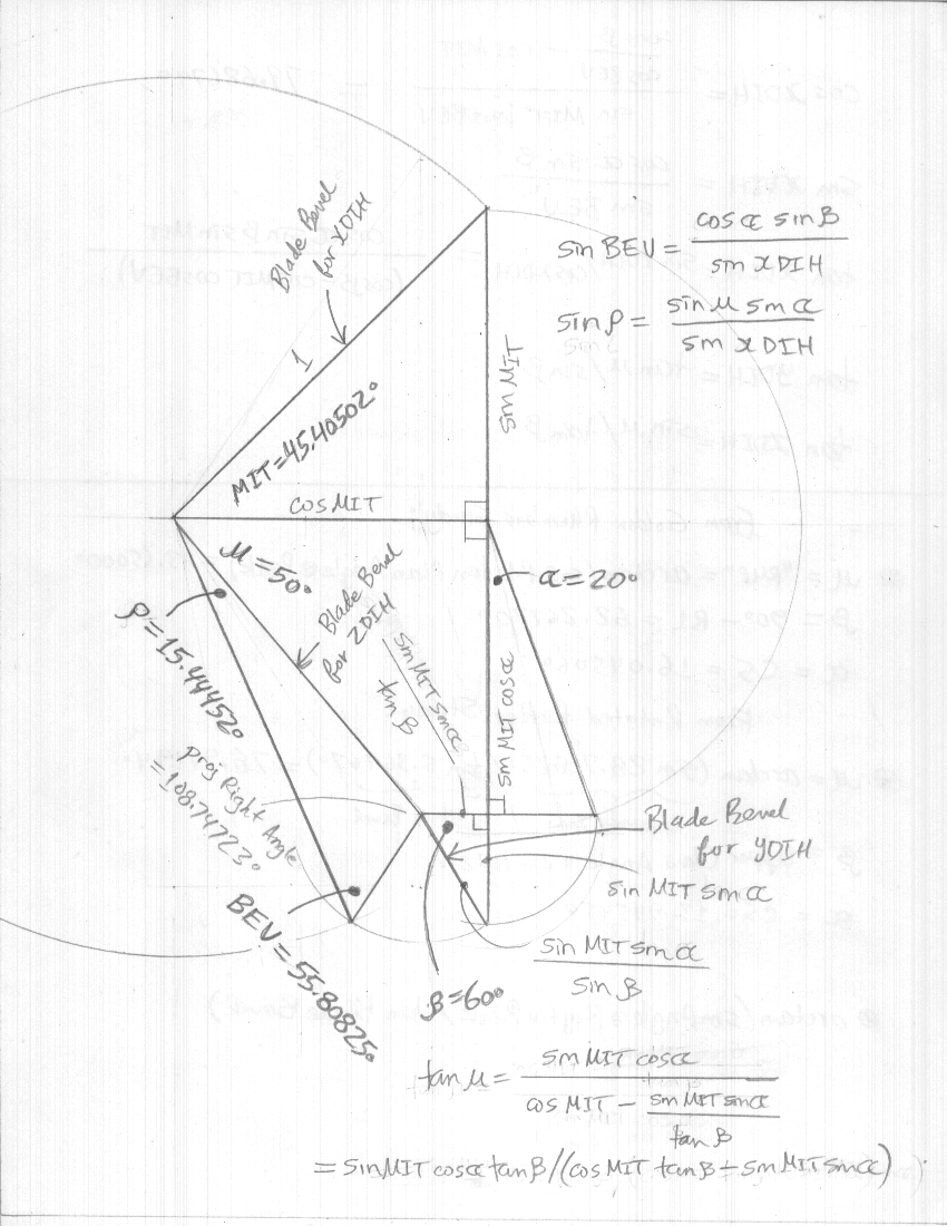
Development of a Pentahedron describing a Non-Rectangular Section, given μ, β and α. After the first few steps the rest of the drawing falls into place.

Setting a different reference length = 1 has produced a few new relationships:
ρ = (90° – BEV) – arctan (cos YDIH ÷ tan β)
Blade Bevel for YDIH = arcsin (tan β ÷ tan (BEV + ρ))
MIT = arctan (sin μ tan β ÷ (cos α cos μ tan β + sin μ sin α))

Test firing the formulas on real Hip roof studies:

Golden Rhombus ... Half-split Roof Angle
μ = arctan (sin (90° – 27.73230°) ÷ tan (90° – 47.05622°) = 43.56300°
β = 90° – R1 = 90° – 27.73230° = 62.26770°
α = C5 = 16.04506°
ρ = Offset Rafter Slope Angle – arctan (tan Main Hip Slope Angle sin Blade Bevel
ρ = 30.79574° – arctan (tan 27.73230° sin (90° – 47.05622°) = 11.08972°
MIT = arctan (sin 43.56300° tan 62.26770° ÷ (cos 16.04506° cos 43.56300° tan 62.26770° + sin 43.56300° sin 16.04506°)) = 40.86615°

70° Offset 12/12 Side Rafter ... Claw Angle Version:
μ = arctan (sin 28.71825° ÷ tan 5.36467°) = 78.94194° (Angle on Upper Shoulder of Offset Rafter)
β = 28.71825° (Upper Claw Angle)
α = 13.99545° (Offset Rafter Backing Angle)
ρ = (90° – Trace Angle on Main Hip) – arctan (tan (90° – Upper Claw Angle) sin Blade Bevel)
ρ = (90° – 55.50766°) – arctan (tan (90° – 28.71825°) sin 5.36467°) = 24.80855°
MIT = arctan (sin 78.94194 tan 28.71825 ÷ (cos 13.99545 cos 78.94194 tan 28.71825 + sin 78.94194 sin 13.99545)) = 57.74662°

70° Offset 12/12 Side Rafter ... Plumb Line Version:
μ = arctan (sin (90° – 43.21918°) ÷ tan 16.86990°) = 67.40640° (Angle on Upper Shoulder of Offset Rafter)
β = 90° – R1 = 90° – 43.21918° = 46.78082°
α = 13.99545° (Offset Rafter Backing Angle)
ρ = Main Hip Slope Angle – arctan (tan Offset Rafter Slope Angle sin Blade Bevel)
ρ = 30.96374° – arctan (tan 43.21918 sin 16.86990°) = 15.71018°
MIT = arctan (sin 67.40640° tan 46.78082 ÷ (cos 13.99545 cos 67.40640° tan 46.78082 + sin 67.40640° sin 13.99545)) = 57.74661°

There doesn’t appear to be a pattern for the formulas for ρ in terms of the roof angles, but:
... 30.79574° and 30.96374° are really 90° – Trace Angles for their respective rafters
... Main Hip Slope Angle and Offset Rafter Slope Angle are 90° – Upper Claw Angle are the complements of the angles at their respective rafter peaks.

ρ = 90° – Trace Angle – arctan( sin Blade Bevel ÷ tan Angle at Rafter Peak)???

Penathedron and Non-Rectangular Section Test
Intersecting Hip Rafters – Warlock Cut, Upper Shoulder Hip B
Angle on Hip B Upper Left Shoulder = 37.65287°
Blade Bevel @ 37.65287° = 55.39851°

μ = arctan (sin 37.65287° ÷ tan 55.39851°) = 22.85244° = Angle on Hip B Upper Right Shoulder ... expected that, the rafter section is rectangular
β = 37.65287° = Angle on Hip B Upper Left Shoulder
α = 0° ... at first glance it might seem like this should be 45°, but there is no backing or rotation angle here

MIT =  37.65287°
BEV = 43.14862° (Trace Angle on Hip A)
ρ = 0°
Projected Right Angle = 136.85138°
Supplementary Angle = 43.14862° (= Trace Angle on Hip A)
Blade Bevel for XDIH = 55.39850°
Blade Bevel for YDIH = 26.71762° (Blade Bevel @ 22.85244°)
Blade Bevel for ZDIH = 55.39850° (= Blade Bevel for XDIH)

The code returned angles for a tetrahedron (which we already know works here). This isn't telling me anything new or lending insight as to an easier means of drawing the intersection.


Although the math takes different routes the following methods agree with one another, this is what I like to see!
– find angles and dimensions to DP lines, complete calculations with Law of Cosines
– solve as for rectangular section with Compound Angle Formulas, apply bevel with Non-Rectangular Section calculator

– solve angles with only the Roof Framing and Joinery Calculator