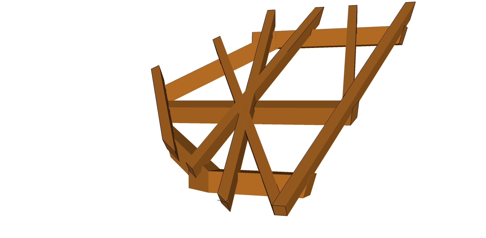
Tuesday, December 23, 2014

Hip Rafter Trace Angles

Last spring Joe Bartok and I studied intersecting hip rafters, rotated 45° from plumb. While studying the intersecting hip rafters, When Hips Collide,  we drew out the geometric development for the Hip Rafter Trace Angles. I didn't realize it at the time, but the geometry for the Hip Rafter Trace Angles can be used for the Witches cut or hip rafter purlin housing angle. The other day when I was drawing out the geometry for the witches cut on a canted hip rafter I needed to check my geometry with a 3D model. Than I begin to think about the Hip Rafter Trace Angles for the When Hips Collide study and sure enough the same geometry can be used for just about any trace angle on a plumb hip rafter or canted hip rafter.


All rafters have a DP- Shadow Line. When the rafter is plumb, the DP- Shadow Line is the same as the rafter run line. The Hip Rafter Trace Angle is developed from the intersection of the DP- Shadow Line of the two rafters and a line that is perpendicular to the DP- Shadow Line of the hip rafter, that intersects the rafter run line at the hip rafter. In the drawing below the hip rafter is canted. The Hip Rafter Trace Angle on the canted hip rafter is the same angle that can be used on the Witches cut. The purlin rafter in the drawing  is rotated into the roof surface at the same angle that is used for the rectangle rafter tails of the Witches cut.


In this drawing I tested the theory on a plumb hip rafter and yes it works correctly on plumb hip rafters.


In the drawing below the roof  slope is unequal and the hip rafter is plumb. Using this drawing technique it makes it pretty easy to draw out the Hip Rafter Trace Angles for the Witches cut or hip rafter purlin housing angle.


Sunday, December 21, 2014

Pent Roof with Rising Purlin

King Class
Pent Roof with Rising Purlin

Die Konigsklasse
Pultdach mit ausgesteller Spitzgaube

Definitely got side tracked going through this task model. I wanted to see how the shadow line technique worked with other drawings that aren't in Bernd Kuppers book on the ancient knowledge of roof framing.  One of my other German books on Schiften uses the typical TC, traite carre, method to develop the DP, "devers de pas", line for the canted rafter. Bernd said this shadow line technique was ancient knowledge and not documented in other German Zermmermann  books.  The German technique for developing the DP-Shadow line of the canted rafter from the other German book I have uses the term Spurlinie, track line. I think the terms shadowline, Schattenlinie, or DP, "devers de pas" are easier to remember and make the drawings easier to reference, then using the term track line. Using Bernd's technique for developing the DP-Shadow Line will save you countless hours of drawing out the DP-Shadow Line . For the carpenters going to the WorldSkills competition it would be foolish not to study the Shadow Line technique where you only have 20 or so hours to draw and build the complex task model. 


3D drawing of the task model.

Geometry developing the rising purlins from the shadow lines.

3D drawing showing the canted plane of the canted rafter for the end cut on the rising purlins.


Drawings that I did while I was side tracked studying the shadow line technique. In this drawing there are four different methods for developing the DP-Shadow line.  

  1. TC-- trait carré method.
  2. Hip Rafter Backing triangle with the Hip Rafter material rotated into the roof surface plane.
  3. Shadow Line method.
  4. Fourth method, in red, with no name. This method works on 90° eave angles, which would be the same as the Shadow Line method. It works in this drawing with an eave angle of 70°, but it didn't work on an eave angle of 60°. Needs more development.


Drawing using the Shadow Line technique and plumb jack rafter claw development for the canted hip rafter.


Drawing showing the three different techniques for developing the DP-Shadow Line of the canted hip rafter on an eave angle of 90°.

 More drawings showing the development of the jack rafter claws on a canted hip rafter with an evae angle that is not at 90°.  The axioms are from this page on the Verkanteter Gratsparren


This is where I really got side tracked. I tried using the witches cut techniques from the book for developing the witches cut on the canted hip rafter and it works correctly for the  witches cut for the canted hip rafter. 


Saturday, December 13, 2014

The folding roof -- sloping ridge roof part 2

King Class
The folding roof (sloping ridge roof)

Die Konigsklasse
Das Turmdach als Faltdach


Finally finished this task model. The canted rafter is developed on the folding roof surface plane. Bernd Kuppers does a really good job in labeling the drawings with the use of TH and BH. In the fourth drawing below you can see how easy it is to label the lines using TH, BH, TS and BS and then transfer these lines  to the timber. I've always had a hard time remembering which lines were for the top of the heel cut. But using Bernd's labeling method makes it a no brainer to transfer the lines from the drawing to the timber.


TH = Top heel is produced by the intersections of the heel bevels with 
the rafter top edge (eave), and then runs parallel to the surface edge. 

BH= Bottom heel is produced by the intersection points of the rafter bottom edge 
with heel bevels in the ground, it is folded at right angles to the rotational 
axis into the plane and then drawn parallel to the surface edge.


Drawings showing canted rafters on the fold out roof surface for clarity. The canted rafter is any rafter that does not have a vertical edge. In these drawings the purlin, parallel to the eave, is developed on the draw down folding roof or fold out roof using the same TH = Top Heel Line and BH= Bottom heel Line for the heel cut at the hip or valley rafter. The skewed canted rafter, yellow, is just a purlin rafter skewed from the eave-plate line. The purlin rafter and canted skewed rafter have the top edge of the timber rotated into the roof surface plane. These drawings are just for clarity using the fold out roof surface method. Stick with the draw down roof surface plane used in the book.  The BH= Bottom Heel line is a lot easier and faster to develop on the draw down folding roof surface plane.


Thursday, December 11, 2014

The folding roof -- sloping ridge roof

King Class
The folding roof (sloping ridge roof)

Die Konigsklasse
Das Turmdach als Faltdach

This task model from the book "The new Book on the ancient knowledge of Roof Framing" is interesting. The base geometry for the ground plan reminds me of the ground plan for the Alhambra, Granada Spain over the Hall of  Abencerrajes. The Alhambra ground plan is two squares rotated in the circle to form the 8 hip rafters and 8 valley rafters. Ad Quadratum ground plan.


In this task model the main ground plan is developed from two rectangles rotated at 45°.

Here's the actual task model ground plan from the book.

Here's the similar geometric development to the Alhambra Granada for the roof design.


Here's the geometric develop that I've done so far. Bernd Kuppers shows all the steps to produce the following roof layout drawings.


Valley rafter development.


Plumb jack rafter claw geometric development.