Sunday, January 10, 2016

45 Plan Angle Rake Wall Plates


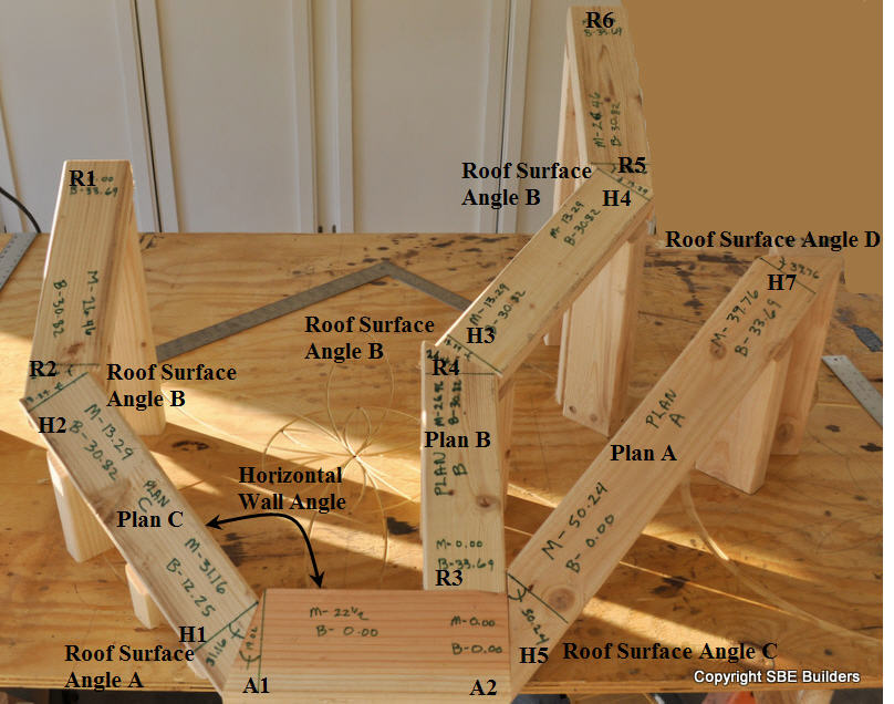
Yesterday, I was building the rake walls for a corner fire place. I have studied rake wall plates rotated into the roof surface plane quite extensively. However, yesterday I just couldn't remember how to calculate the rake plate miter angles. So this post is a reference for me the next time I'm on the jobsite building rake walls rotated into the roof surface plane.


Here's a drawing of the corner fire place I was building. The roof slope angle was 26.56505°, 6:12, with a 135° eave angle for the wall rake plate rotated into the roof surface.


Saw Miter Angle for Common Rafter Pitch Rake Wall = arctan ( tan (Direction Of Saw Travel ) ÷ cos (Roof Slope ))

R2 = Saw Miter Angle for Common Rafter Pitch Rake Wall = arctan ( tan (22.5° ) ÷ cos (26.56505° )) = 24.84908°

R2 = Saw Blade Bevel Angle = arcsin ( sin (26.56505° ) × cos (22.5° )) = 24.40422°

Saw Miter Angle = 180° - Real Roof Surface Angle - Saw Miter Angle for Common Rafter Pitch Rake Wall
H2 = Saw Miter Angle = 180° - 138.18969 - 24.84908= 16.96123°
H2 = Saw Blade Bevel Angle = arcsin ( sin (26.56505° ) × cos (22.5° )) = 24.40422°


A1 = Saw Miter Angle = arctan ( cos (26.56° ) ÷ tan (67.5° )) = 20.32886°

A1 = Saw Blade Bevel Angle = arcsin ( sin (26.56° ) × cos (22.5° )) = 24.3996°


Saw Miter Angle = 180° - Real Roof Surface Angle - Saw Miter Angle for Common Rafter Pitch Rake Wall

H1 = Saw Miter Angle = 180° - 131.81031 - 20.32886= 27.86083°

H1 = Saw Blade Bevel Angle = arcsin ( sin (26.56° ) × cos (67.5° )) = 9.85418° 


Hip Rake Wall Studs
Hip Rafter Pitch Angle = arctan( tan( Pitch Angle ) * sin( Plan Angle ))
Hip Rafter Backing Angle = arctan( sin( Hip Rafter Pitch Angle) ÷ tan( Plan Angle ) ) 
Hip Rafter Plumb Backing Angle = arctan( tan( Pitch Angle ) * cos( Plan Angle ))

Hip Rake Wall Pitch Angle = arctan( tan( Rafter Pitch Angle ) * sin( Working Angle ))
Hip Rake Wall Pitch Angle = arctan( tan( 26.56505.69 ) * sin( 45 )) = 19.47121°
Rake Stud Saw Miter Angle = Hip Rafter Plumb Backing Angle = 19.47121°
Rake Stud Saw Blade Bevel Angle = arctan(cos(Hip Rafter Plumb Backing Angle)* tan(Hip Rafter Pitch Angle))
Rake Stud Saw Blade Bevel Angle = arctan(cos(19.47121)* tan(19.47121)) = 18.4349°


Saturday, January 2, 2016

Divers Hip Rafter Boucher

This method of drawing out the divers hip rafter was shown to me by Olivier Phojo. He said the French compagnon-Professor J.D. Boucher (1890?), developed it. This method of drawing out the diverse hip rafter using the Sauterlle method, bevel square, is brilliant. Boucher may have developed the method, but Olivier drew it out were I could easily understand it. I looked through Boucher's book , L'art Du Trait of Charpente, yesterday and I couldn't find this method in his book.


This method of drawing out the bevel square angles for the divers hip rafter only takes a couple of minutes. 5 minutes at most. It's something Billy and I should teach in our roof framing geometry classes.  


Start off by drawing 2 perpendicular lines. You can draw this on a piece of paper 24" x 18". Then place the framing square on the vertical line and the end point of the framing square on the horizontal line. Trace the framing square for the profile rafter roof slope angle. In this task model I use and 8:12 pitch (33.69007°).


Next draw a perpendicular line to the roof slope line. This line will represent the eave line. I used 12" in this task model for an equal pitched roof. Then connect the eave line to the rise of the roof slope triangle. This line will represent the hip rafter on the roof surface.


At the intersection of the hip rafter on the roof surface with the horizontal line draw a perpendicular line equal in length to the roof slope triangle's tangent. 6 21/32", or 6 11/16" in this task model.


Then draw the diverse hip rafter bevel square lines connecting back to the roof surface triangle.


The red angle is used for the miter angle on the side of the diverse hip rafter. The blue angle is the top bevel on the diverse hip rafter.

The orange angle is used for the miter angle on the side of the diverse hip rafter and the blue angle is used for the bevel angle on top of the divers hip rafter for the first face cut at the head of the divers hip rafter. For the second face cut use the brown angle on top of the diverse hip rafter and the miter angle on the side of the hip rafter will be 90°.


Another drawing using a different roof slope angle. The DP line is easier to understand in this drawing. You don't need to draw the DP line, but you can check your cuts with the DP line.


Here's a picture of laying out the miter and bevel angle on the foot of the hip rafter using the red and blue angles. The cut will be a parallelogram, so you use the same angles on the top and bottom of the foot cut.


Here's a picture of the layout for first face cut at the head of the rafter.


Bottom view of the rafter layout.


The cut at the foot of the hip rafter is complete and the first face cut is complete.


Checking to make sure the foot cut aligns wit the eave line and DP line in elevation view.


Checking to make sure the first face cut is plumb to the horizontal plane.


For the second face cut you use the brown angle or 90° to the first bevel cut on top of the rafter.


Second face cut laid out.


I checked the accuracy of my drawing using a digital bevel square.


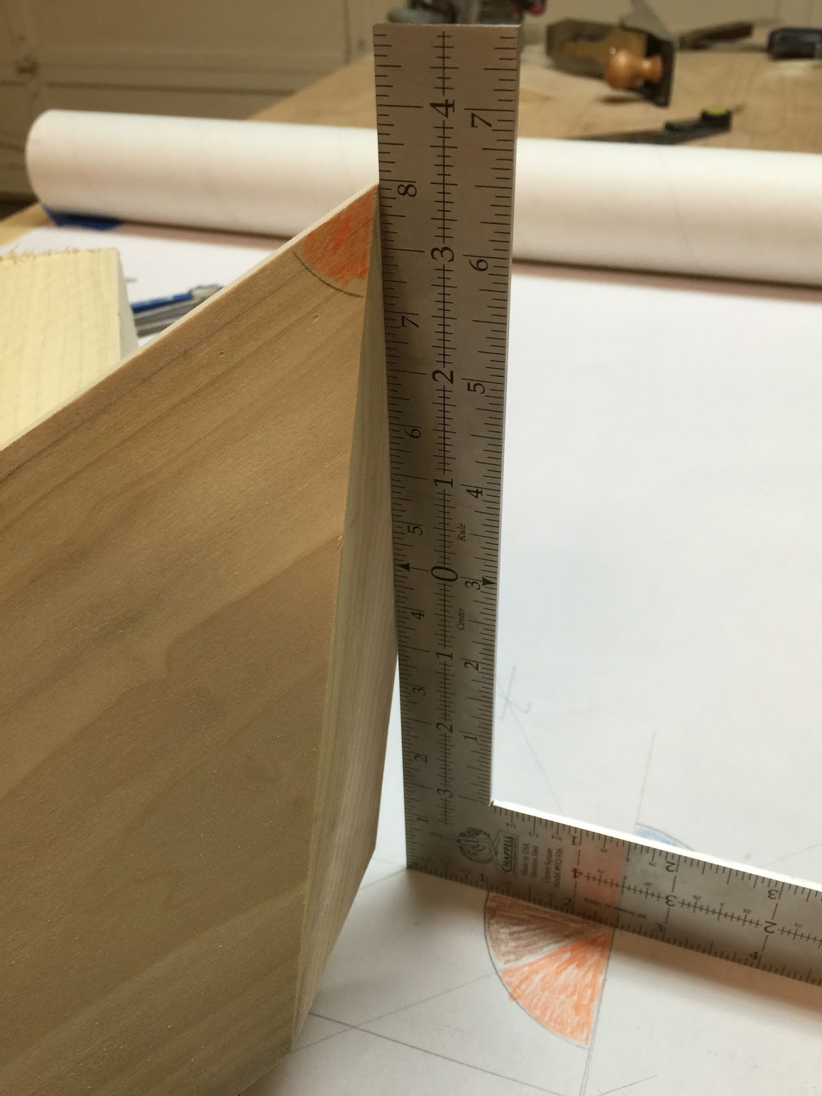
I then used a skill saw for all of the cuts. You could align the blade for the saw blade bevel angles on the timber, but using some math makes somewhat easier.

For the divers hip rafter foot cut I used.
Miter Angle 27.1°
Saw Blade Bevel Angle  = arctan(sin(27.1) ÷ tan(50.24) = 20.7 °

For the divers hip rafter face cut #1  I used.
Miter Angle 49.07°
Saw Blade Bevel Angle  = arctan(sin(49.07) ÷ tan(50.24) = 32.1 °


For the divers hip rafter face cut #2  I used.
Miter Angle 90°
Saw Blade Bevel Angle  = 39.7 °

Here's a link to a PDF file that you can print out for this task model layout.
Boucher 8:12 Pitch


Here's a wire frame drawing of the Boucher technique. Your folding the canted plane flat to the plumb plane of the hip rafter. I'm guessing you can use this same technique for just about any canted rafter.


Another example of folding the purlin rafter (frieze block, bird's block) plane flat. Pretty easy, only 3 triangles.


Sunday, December 27, 2015

Divers Hip Rafter # 2

I was redrawing the Divers Hip Rafter files to scale them down for a task model and found a way to eliminate one of the arc's that's drawn to define the divers hip rafter profile.  With a perpendicular line to the DP - Shadow Line through the center point of the hip rafters in plan view and an Arc with the radius equal to the length of the plumb hip rafter profile length, the intersection of the single Arc and perpendicular line defines the divers hip rafter profile. A lot easier than using two Arcs to define the diverse hip rafter profile.


Saturday, December 26, 2015

Divers Hip Rafter

Developing the diverse hip rafter in profile.

 I wanted to develop the divers hip rafter (canted hip rafter, hip rafter rotated into the roof surface) without using the bevel square method (grasshopper -"la sauterelle") or using the roof surface ( draw-down or fold out method). Michel Verdon at , French Timber Framing Traditional Scribing , helped me and now it's pretty easy to draw out the divers hip rafter fully developed in the profile elevation only.

Retobois Charpente Couverture Ramonage
on Facebook posted this dormer with the diverse hip rafters rotated into two different roof surface planes and said it was quite common in France.  The hip rafter on the right side of the dormer is rotated into the roof surface on the front of the dormer and the hip rafter on the left side of the dormer is rotated into the roof surface of  the left side of the dormer.

Retobois Charpente Couverture Ramonage Diverse Hip Rafter on Facebook


Both divers hip rafters are cut exactly the same. The foot and head cuts on the diverse hip rafters only need to be developed one time. Layout and cut both divers hip rafters exactly the same and rotate them into place.


One of the reasons I didn't want to draw out the geometry for the divers hip rafter using  the bevel square method (grasshopper -"la sauterelle") , because I could just as easily use my RafterTools+ app on my iPhone. The divers hip rafter is the same length as a plumb hip rafter. So, you only need to know the angles to cut the divers hip rafter. In fact, to draw out the geometry of the diverse hip rafter in profile you need to know how to draw out the plumb hip rafter in profile.


RafterTools+ on iPhone

Main Slope Angle = 30°
Adjacent Slope Angle = 30°
Main Plan Angle = 45°
Adjacent Plan Angle = 45 = °
Hip Rafter Slope Angle = 22.20765°
Hip Rafter Run = 60 ÷ cos(45°) = 84.85281
Hip Rafter Length = 84.85281 ÷ cos(22.20765°) = 91.65

Treteaux Angles
R8-DP = 23.57818
PSBa-DP = 19.10661
R11m-DP = 52.62876
P11m-DP = 40.89339
P15a-DP = 49.10661

The only math - trigonometry you need to use is to calculate the saw blade bevel angle for face cut #1.
Face Cut #1
Angular Dimension (52.62876°)
Miter Angle 52.62876°
Saw Blade Bevel Angle = arctan(sin(52.62876°) ÷ tan(49.10661°)) = 34.53757°


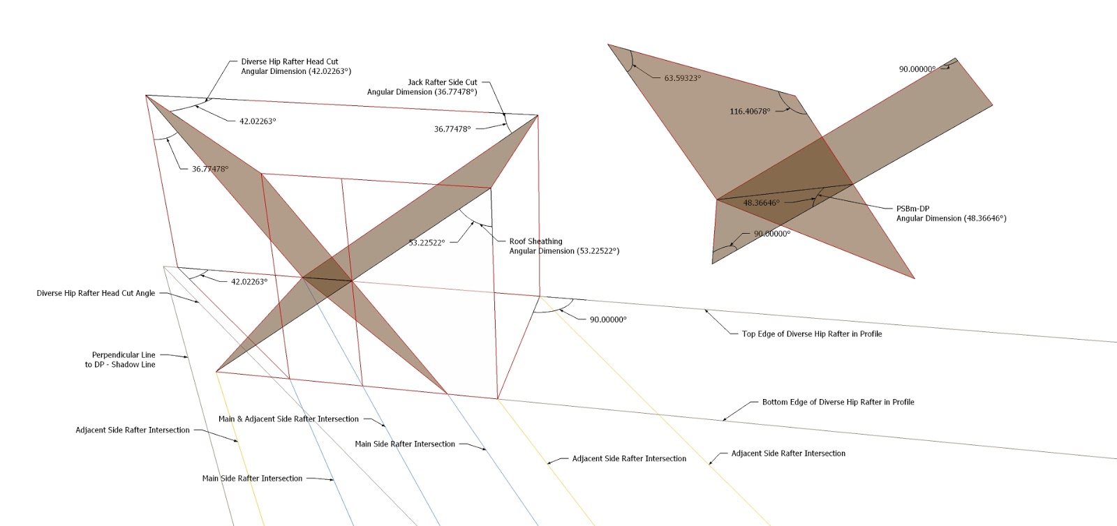
 To draw out the geometry for the diverse hip rafter in profile I'm using the shadow line technique from Bernd Kuppers book to locate the DP-Shadow line of the canted hip rafter. After the DP - Shadow line is drawn, draw out the plumb hip rafter profile. Then draw out the plane tilt of the diverse - canted hip rafter and use the intersection of the two arc's to finish the diverse hip rafter profile.


 Here's a drawing showing how to lay the timber on top of the profile drawing of the divers hip rafter and transfer lines from the drawing to the timber for the layout on the foot cut of the divers hip rafter.


 Drawing with the diverse hip rafter head cut developed by using lines perpendicular to the DP-Shadow line.


Both sides of the diverse hip rafter head cuts developed in plan view.


After developing the geometry for the dormer I wanted to see what the head cuts on the divers hip rafter would look like when it intersects a king post.  The angles are the same at the foot and head cut of the diverse hip rafter.


After drawing the geometry for the divers hip rafter intersecting the king post, I drew out the geometry for a jack rafter on each side of the diverse hip rafter.


The geometry in this drawing makes it pretty easy to draw the head cuts of the two jack rafters. Including the upper and lower claws.