In German the Draw Down Technique is called Abklappung . Which translates to Enlightenment or Elucidation. It's absolutely an Elucidation to the drawing and cutting of timbers in the roof surface. Stereotomy, the Art du Trait or Art of Line should/must be studied, but the Draw Down method is a technique that we can use on full size roofs that we frame everyday.
When I first started the task model drawing yesterday, using the Draw Down Technique, with all of the lines right on top of each other I got lost in the thought process and used my H1 dimension for the height of the claw angle where it intersects the hip rafter. My H1 dimension is the plumb height on the hip rafter minus the depth of the hip rafter backing line. It should only be used on rafters that are plumb to the earth, not on rafters that are perpendicular to the roof surface. Then I started to use the hip rafter housing angle dimension from the purlin study and I realized that dimension only worked if you already knew the hip rafter housing angle for the rotated rafter, which I did/do not know. Only a full Devers De Pas drawing would give you the angle, which I did not intend to include in this drawing.
Back to the drawing board.
After drawing out the Draw Down Roof Surface over the plan view of the task model, it became evident that the amount of lines crossing each other were confusing, so I labeled all of the lines on the task model drawing board. Tony and Dan teacher their apprentices to use colored pencils for the different lines on the roof surface, but all of my color pencils have too soft of a lead to make accurate lines on the drawing board. Need to find color pencils with a harder lead.
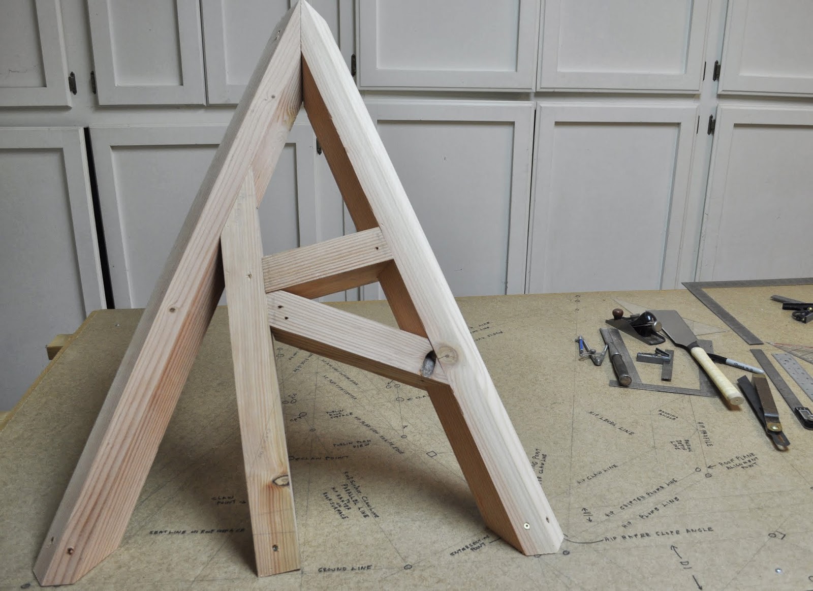
The second mistake I made on the task model drawing was by not drawing in the seat line on the roof surface for use with the main rotated rafter. Instead I used the plan view seat line to mark off the seat of the rotated rafter and when I put the task model together it was more than obvious the seat cut was wrong. So I had to cut an 1 1/2" off the level cuts of the rafters with my BigFoot Beam Saw. So, the task model doesn't fit the plan view lines in the drawing. Nor is the seat cut perfect on the rotated rafter.
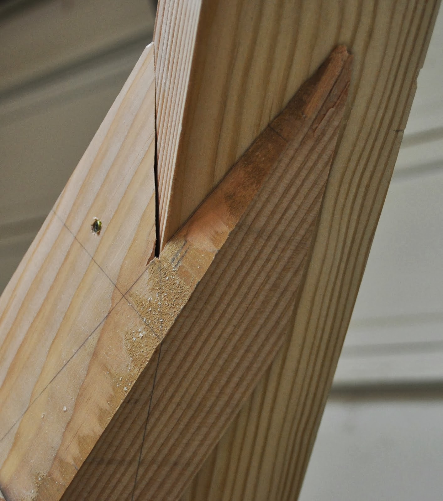
Anyway, the real game changer is how easy it is to mark the miter and claw angles on the timber using the Draw Down method. After you draw out the correct lines for the Draw Down Roof Surface , it's simply a matter of drawing perpendicular lines on both sides of the timer at the location of the seat line, miter line or claw line. No, stereotomic or true shape drawings off to the sides of the roof surface, that easily lend to confusion of which perpendicular lines to use for the true shape of the timber on the roof surface. This happens a lot with roof bevel angles that are greater than 80°. The lines are so close together it's hard to tell which line to use for the true shape of the 3D drawing.
Draw Down Technique drawing steps:
- Draw the Plan View of the Hip Rafters
- Draw the Profile of the Common Roof Rafter.
- Draw the center line edge line of the hip rafter on the roof surface.
- Draw the perpendicular lines at the foot of the profile rafter that establish the dimension for the internal edge of the hip rafter on the roof surface, plan view seat line, roof surface seat line.
- Draw the Hip Rafter in Profile to transfer a perpendicular line for the intersection of the hip rafter on the roof surface for the claw lines.
- Draw the internal edge of the hip rafter on the roof surface.
- Draw the claw lines on the roof surface.
- Transfer the rotated rafters from plan view to the roof surface view using perpendicular lines.
- Draw out the sides of the rotated roofs in roof surface view using a scrap of lumber the same width as the rotated rafters.
- Draw perpendicular lines on the side of the timber placed directly over the roof surface view of the rotated rafter for the seat lines, miter lines and claws lines.
- Draw the back bevel lines on the top and bottom of the timber from the perpendicular lines on the sides of the timber.
- Cut & assemble the roof rafters.


Here's a couple of drawings showing how I would/could easily add rotated rafters to a Hexagon Roof or a simple hip roof.


No comments:
Post a Comment
Note: Only a member of this blog may post a comment.