Thursday, June 19, 2014

The Leaning Tower of Mayen

Bernd Brück from Germany , a German Zimmermann (Carpenter), sent me a PDF file with the story of rebuilding the Leaning Tower of Mayen after world war 2. It's pretty interesting, on how the roof framing geometry is designed by rotated and offset Octagons, which in turn forms the leaning twisted spiral tower. 

I've translated the German text to English with the Google Translator.
_____________________________________________________________________

The Leaning Tower of Mayen 
Der schiefe Turm von Mayen

Post 1 January 1953

A unique carpentry task

When speaking of crooked and twisted spires, the name Mayen will always fall. In a number of publications, the "German Master carpenter "about this unique ancient monument reported in the bombing of the last war,  with a large part of the Old Town, this sexy Eiffel tower rubble fell. 

The Mayener are tough. Thus grew because soon after the war the tower walls of St. Clement's Church again in the sky, only the spire, the crowning of the building, was still missing. In the spring of vergangenen Year it came down to it, that one is more detailed thoughts about his design made. Some were for a new, straight-building;

However, the majority of Mayener wanted known landmark of Mayen, the "leaning See built on · again. Ancient form tower ". For a version in steel, to which one first had thought, in particular the men turned ·Gehrüder Rosenbaum, Zi ~ ergeschäft and sawmill in Mayen, the later the execution of the new wooden tower Helms took over. Design and static Calculation was in the hands of the Consulting in Karlsruhe. Was originally thought only the rotation of the spire to restore and to refrain from the Uber slopes of the peak, so should now be the new spire of the old as possible same. 

Well yes Turmkons constructions anyway not an everyday Task, but twisted and crooked already not at all. According to the literature on verdrehte towers it's almost been exclusively design flaw, led to deformation - such had of course, be avoided. Only about a 100 year old work, "The work of art in all rooms its parts "vori Andreas Romberg, we could remove some recb.l valuable information. 

The author has sieve in this extensive Bum also with the., Construction wooden Thunuspit ~ s "concerned and a number heed cheaper receivables aufgestellt, of which we will mention only a few. So should the construction in Inner possible glues held however, the roof panels are self-reinforced to the commission of the tower and the later ere control the components not to unnecessarily obscure; the Longitudinal forces should only end grain to end-grain be rendered in order not dUrd: l uneven Subsidence occur later Vertormungen; according to several years overdue repair work is it width that all woods are connected so that they can be easily replaced without di ~ Star: dfestigkeit of the building while impaired ~ ud. Hmzu came in the case Mayen still the verständhche Request of the executive master carpenter by Aufrichtarbeit easier. 

The result of all considerations led us first to two designs. The first draft was the roof sheathing used for carrying with it So was a nailed-shell structure; scheduled were 8 struts, on which at a distance of about 80 cm planks nailed wreaths are placed should. The advantage of the light and the Abbunds extensive adaptability to the shape of the old spire stood but they also have disadvantages. So have the quest, as they no shock to Break point had to be carried out, a large obtain overall length and makes the erection; the upper part of the tower would be because of the Anhäufunq of structural timbers at the break point not from the inside been accessible; Finally, it would later have may be adversely affected during repairs, down when D1E whole construction into the roof had. 

For this reason, we chose the second design, the design shown, - everyone could connect receivables in happier ways. 

The Rising masonry has an exterior of  rd. 6.45 X 6.75 m, that is not exactly square. to the supports of the belfry - a reinforced concrete ring beam, of 24m above the ground is - is the wall thickness of 1.00 m. Furthermore rise in the four sides of the tower, the 70 cm thick pediments with the scarf holes. From Glockenstuhlauflager to up the gable peaks are 6.00 m. The wooden tower construction consists of a lower part with joists above the belfry; also rises the real helmet with a height of 21.00 rn., it is divided into 5 equal floors, each 4.20 m.

The substructure is the Dbergang of the square base of the tower to the eight-vertex of the helmet. The outer diameter of the octagon circumscribed circle was 6.60 m laid down; the difference - which arises from the fact that the superstructure regularly, the base is irregular - was settled by the roof membrane, since otherwise have been without the vevgrößert! ün existing difficulties in joinery unbearable would.

In the tower corners and in the middle of the tower walls are in the area of ​​the bell chair Post net and arranged by joists and ceiling joists connected to. The in Middle wall standing posts (Fig. 1) are in each case by two struts on the corners the tower sought. In the tower corners are strut post after a slight angle
to put inside the tower and connected to the corner posts by short Pliers: wear an octagonal section steel rafters, the remaining four corners support equipment to the concrete by reinforced gables rest. The frame measures transmits the loads on the upper Turmkon-construction (Fig. 2) on the bottom and takes the here
ensuing horizontal forces. Here in the gable-triangles and anchored to the corner posts. The corner post in turn anchorages integrated into the reinforced concrete ring beam.

The upper part of the tower construction, the actual helmet is made, on the one hand from the supporting structure with the Pfettenkränzen and partly from the rafters with the roof skin (formwork, cardboard, slate). For the first three floors above profile steel frame is selected a network whose vertices per floor 1/16 are shifted from each other so that the ridges perform the desired rotation. The two lower floors are centrally übereinan the while the third is already 20 cm to the east ver-Is' choben!. From the third floor up to the helmet tip no more distortion is present. Here were the Füllhölzern of goats on the third floor of the pursuit of the Kaiser handle high out. The spire hangs by a total of 1.40 m to the east.

The key to the whole construction are the goats of the lower floors (Fig. 4 & 6). They are re regularly, ie the two trestle legs are of equal length and nestle Up to a Füllholz to with which they each by two and two hardwood dowels (Bearing capacity speed about 1000 kg), respectively. In this way, it was possible not only by all of the loads To transfer grain to grain, but but also considerable tensile forces within the include construction, are expected to arise in particular because of the one-sided tilt had.

Each floor encircling Pfet are tenkränze (Fig. 4 and 5) and each one crosswise stiffened bottom (Fig. 3) arranged net whose stiffeners also cables with nozzle are connected. The floors are strong up to a manhole with 3 cm, strong nailed floor coverings provided.

From the Füllholz of goats on the third floor of läilfen after Helmet tip struts halfway again by a recent purlin
held together ten are at the ridge and out of the bolt and components are connected by more a keyed round steel ring be taken. The struts for receiving twisting forces with Andrew's crosses in 4 levels verschwertet.

Because of the inclination of the upper part of the helmet was the only otherwise required above Kai serstiel up in the covering over the bell chair brought down; thereby became even better achieved anchorage.

The entire construction including the roof sheathing is with a proven Wood preservatives · salt impregnated on base in the immersion process short.

The belfry itself was a steel-construction carried out.

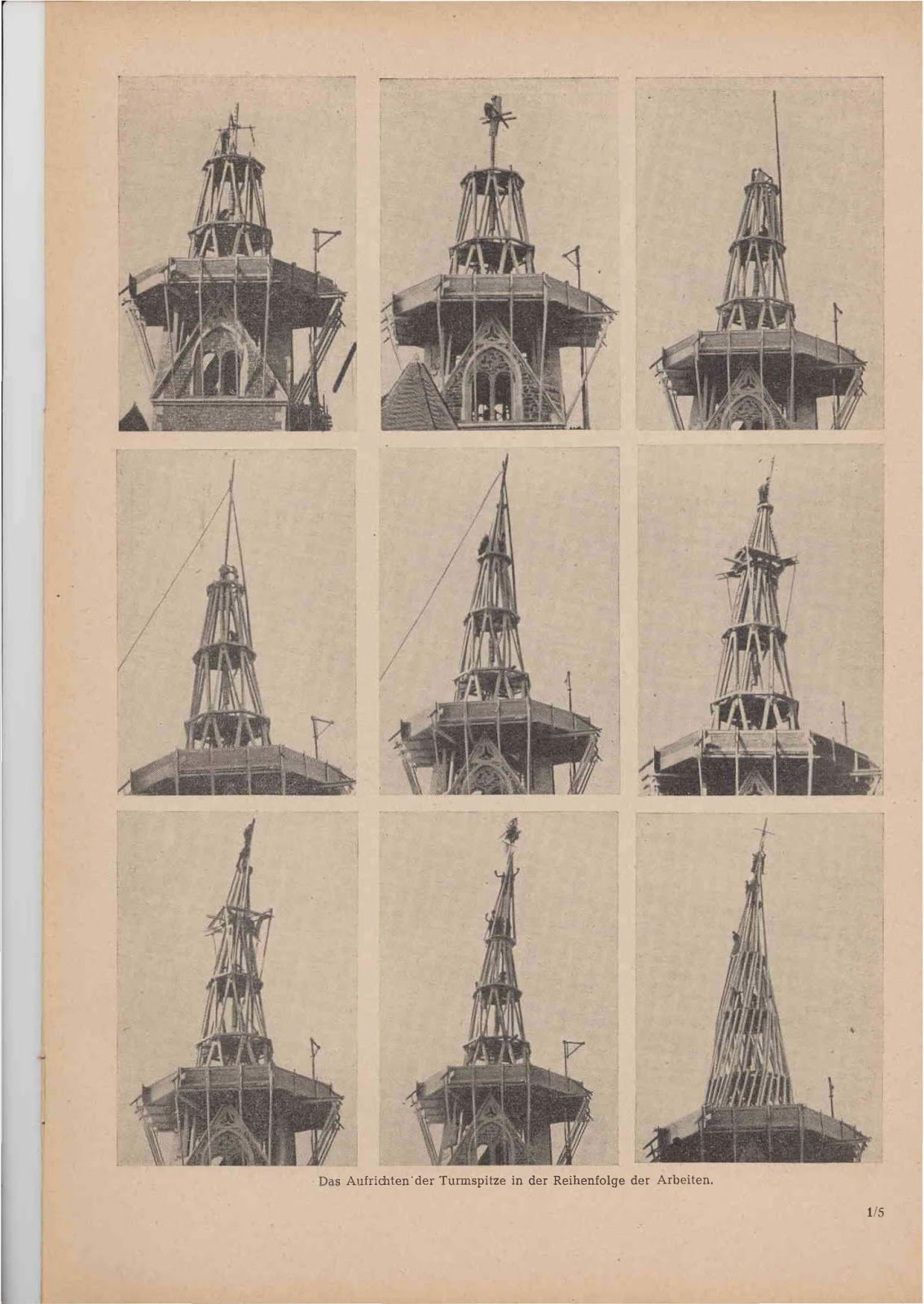
The Abbundarbeiten were not like at such a fancy design is to be expected, not very easy. In contrast, the erection went larly proportionate very painless; that was not last well on the exemplary work stand and the
spacious work platform at the level of the summit peaks. Woe: lort stood up, did not in any event  the impression that he is already SID1 be 30m above the ground.

Each timber had been overcome with the help of a construction and electric drive pulled up. According to which the lower part of the construction of the tower, inside and auf.gestellt the profile frame was attached in pairs-the bucks of the first floor were each represents and connected by the Aussteifungshölzer with the Emperor stalk. Similarly the next two stories were set up what essentially without zusätzlidle Scaffolding could go on. The setting up of the third and the overlying Floors can be seen alfs the attached pictures.

To align the struts and the Imperial stem still an auxiliary mast had to be made. From the series follow the images is clearly evident how this issue on the individual has been resolved. Above the third floor was to carry out the further Are work even created a small work platform, because the space there, as also from
the pictures shows it was no longer too plentiful. Finally, were the top attached the rafters down, with at each purlin flat steel anchors are fixed, and finally in the order gleidler are, and finally in order the gleidler applied formwork.

The Reconstruction went smoothly and without any accident withstanding. Meanwhile, the building has been in the first violent storms proved. Let's hope that the tower in the future all storms withstand and an equally venerable age reaches its like before predecessor. 

The check digit on cutters
Large cutters, Abplattköpfe, knife shafts, slotted discs, etc. carry in most cases the
Approval of the factory producing factory, for example, n = 4000., This means that the concerned Fende
Tool has been tested for safety in a one-minute speed of 4000.

., N "is the technical term in the calculation formulas for every minute rotational speed of the tool, ie., n = 4000 "means 4000 every minute rotations of the Tool.

Since this check number, the maximum allowed speed in Indicates idle, every minute must the tool concerned with more than 3000 Run turns. Dignity., N= To work 4000 ", then would the tool cut excessively and will burn hot. · The rotation speed may therefore only be höd1stens 3/4 be the specified check digit. Importantly, the tool factory in order is placed indicating the speed of the engine.


Thursday, June 12, 2014

Rake Crown Mouldings with No Transitions

 Crown Moulding Tools help file for Rake Crown Moulding with no Transition pieces. Sloped ceilings with rake crown moulding with transition pieces looks good, however a sloped ceiling with rake crown moulding with no transition pieces looks even better.


Crown Molding Tools for Android 


Crown Molding Tools for Android has been updated with 6 new calculators. Installing rake crown moulding is complex, but these calculators will hopefully simplify the task.
  1. Calculate Horizontal to Rake Wall No Transitions
  2. Calculate Rake Wall To Horizontal at Corner Wall No Transitions
  3. Calculate Rake Crown to Rake Crown No Transitions
  4. Calculate Rake To Level No Transitions
  5. Calculate Rake To Level Return No Transitions
  6. Calculate Rake To Rake at Peak No Transitions


These pictures were taken at The Moulding Company  in Concord California. The rake crown mouldings were installed by Christian Murtha.


For rake ceiling crown moulding with no transitions, you have to roll the crown moulding to a different spring angle for the length of the crown moulding miter cuts to be the same length. The crown moulding positioned on the lower horizontal wall will be set at the spring angle of the crown moulding. The shallower the spring angle of the crown moulding the roll-tilt of the crown moulding running up the rake wall will look better. Crown moulding with a spring angle of 38° should be your first choice. The rolled crown spring angle is equal to the Crown Moulding Spring Angle + Rake Ceiling Slope Angle. With an 38° spring angle and a roof slope angle of 33.69007°, 8:12 pitch, the rolled crown spring angle is equal to 38° + 33.069007° = 71.69007°. With a 45° spring angle it would be equal to 45° + 33.69007° = 78.69007°.

All of the crown moulding should be back beveled to set tightly against the ceiling. Use the Crown Slope Reference Plane Angle to back bevel the top edge of all of the crown moulding.

Start with the lower horizontal crown moulding. Place the lower horizontal crown moulding against the wall and scribe the bottom of the crown moulding for a reference line. Draw parallel lines from the rake ceiling for the rake crown moulding. Do not use the same dimension as the  horizontal crown moulding reference line for the rake ceiling reference line. These are parallel lines determined by the intersection of the bottom of the horizontal crown moulding with the rake ceiling wall.


Roof  Pitch  in Inches per Rise of  Roof in 1 Foot of Run -- Roof Slope Angles
  • 0.5:12 = 2.38594°
  • 1:12 = 4.76364°
  • 1.5:12 = 7.12502°
  • 2:12 = 9.46232°
  • 2.5:12 = 11.76829°
  • 3:12 = 14.03624°
  • 3.5:12 = 16.26020°
  • 4:12 = 18.43495°
  • 4.5:12 = 20.55605°
  • 5:12 = 22.61986°
  • 5.5:12 = 24.62356°
  • 6:12 = 26.56505°
  • 6.5:12 = 28.44293°
  • 7:12 = 30.25644°
  • 7.5:12 = 32.00538°
  • 8:12 = 33.69007°
  • 8.5:12 = 35.31121°
  • 9:12 = 36.86990°
  • 9.5:12 = 38.36749°
  • 10:12 = 39.80557°
  • 10.5:12 = 41.18593°
  • 11:12 = 42.51045°
  • 11.5:12 = 43.78112°
  • 12:12 = 45.00000°
  • 12.5:12 = 46.16914°
  • 13:12 = 47.29061°
  • 13.5:12 = 48.36646°
  • 14:12 = 49.39871°
  • 14.5:12 = 50.38931°
  • 15:12 = 51.34019°
  • 15.5:12 = 52.25319°
  • 16:12 = 53.13010°
  • 16.5:12 = 53.97263°
  • 17:12 = 54.78241°
  • 17.5:12 = 55.56101°
  • 18:12 = 56.30993°
  • 18.5:12 = 57.03060°
  • 19:12 = 57.72436°
  • 19.5:12 = 58.39250°
  • 20:12 = 59.03624°
  • 20.5:12 = 59.65675°
  • 21:12 = 60.25512°
  • 21.5:12 = 60.83239°
  • 22:12 = 61.38954°
  • 22.5:12 = 61.92751°
  • 23:12 = 62.44719°
  • 23.5:12 = 62.94940°
  • 24:12 = 63.43495°
Key Words:
Cathedral ceiling rake crown molding miter and bevel angles
Vaulted ceiling rake crown molding miter and bevel angles
Sloped ceiling rake crown molding miter and bevel angles

Saturday, June 7, 2014

Octagon Roof Framing Layover Valley

After looking at the pictures I took of a house last week, that I framed 15 years ago, I thought it would be fun to see how I would now calculate the California Layover Valley Rafters on the equal sided Octagon Roof and the unequal sided polygon roofs with 12 sides. Fifteen years ago I remember calculating the California Layover Sleeper that's parallel to the front plate, but the rest of the hip rafters and sleepers were scribed and cut to fit.

The California sleeper - Layover board are similar to the   discussion of the at JCL - Online Rough Frame forum about 7 years ago.
Round Roof into Gable

and the calculator I developed for that thread.
Sloped Frustum of Pyramid Calculations for Polygons or Cones Roof Framing Geometry based on Complex Roof Geometry 


Here's my view on the basic steps for Octagon Roof Framing without using one of my RafterTools app calculators.

Octagon Eave Angle
(135.00°)
Octagon Plan Angle
(67.50°)
Octagon Roof Slope Angle, Profile Rafter Slope Angle
12:12 Pitch (45.00°)
Main Roof Slope Angle 10:12 Pitch (39.80557°)
Comm Rafter Run
72.4264"
Jack Rafter Spacing = 16" O.C.
Hip Rafter Width = 1.5"

Calculate the king common rafter length for the roof
72.4264" ÷ cos (45.00) = 102.426397"

Calculate the mitered king common rafter length for the roof
0.75 ÷ sin(22.5°) = 1.95984"
1.95984" ÷ cos( 45.00°) = 2.771638"
Mitered King Common Rafter Length = 102.426397" - 2.771638" = 99.654758"

Calculate the rise for the roof
72.4264" x tan (45.00) = 72.4264"

Calculate the hip rafter run
72.4264" ÷ cos (90° - 67.50°) = 78.39377"

Calculate the hip rafter slope angle
arctan(72.4264 ÷ 78.39377) = 42.73420°
or use arctan (tan Profile Rafter Slope Angle x sin Plan Angle)
arctan (tan 45.00° x sin 67.50°) = 42.73420°

Calculate the roof sheathing angle
arctan (tan Plan Angle ÷ cos Profile Rafter Slope Angle)
arctan (tan 67.50° ÷ cos 45.00°) = 73.67505°

Calculate the jack rafter length difference based on the On Center spacing
tan 73.67505° x 16" = 54.62742"

I like to calculate all of my Jack Rafter Lengths using the Roof Sheathing Angle. First you need to calculate the Hip Rafter Offset Along the Eave Line. The trigonometry below only works on equal pitched roofs.

1/2 Hip Width ÷ sin (67.50°) = Hip Offset Along Eave Line
0.75" ÷ sin (67.50°) = 0.811794"
Hip Offset Along Eave Line = 0.811794"
Jack Rafter Length Deduction for Hip Rafter
Hip Offset Along Eave Line x tan(Roof Sheathing Angle) = Jack Rafter Length Deduction for Hip Rafter
0.811794" x tan(73.67505°) = 2.77164"
Jack Rafter Length Deduction for Hip Rafter =  2.77164"

Calculate the Jack Rafter Length for Descending Jacks from the King Common Rafter.
Center of King Common Rafter = 30"
First Jack  15 1/4" from center of King Common Rafter
First Jack Spacing From Corner = 30 - 15 1/4 = 14 3/4"
First Jack Rafter Length = (14 3/4" × tan(73.67505°)) - 2.77164" = 47 9/16"

Calculate the Frieze Block miter angle & Saw Blade Bevel Angles
Frieze Miter Angle = arctan( sin ( Pitch Angle ) ÷ tan( Plan Angle ))
Frieze Miter Angle = arctan( sin ( 45.00° ) ÷ tan( 67.50° ))= 16.32494°
Frieze Saw Bevel Angle = arcsin( cos ( Pitch Angle ) x cos( Plan Angle ))
Frieze Saw Bevel Angle = arcsin( cos ( 45.00° ) x cos( 67.50° )) = 15.69985° 

Calculate the Hip Rafter Plumb Line Shift at foot of hip rafter for Equal Pitched Roofs.
1/2 hip rafter width × tan( 90° - Plan Angle) = hip plumb line shift at foot of hip rafter
0.75" x tan (22.50°) = 0.31066" = or 5/16"

Calculate the Jack Rafter Plumb Line Shift for the Jack Rafter Side Cut Angle.
jack rafter width × tan( 67.50°) =Jack Rafter Plumb Line Shift  = 3.62132 = 3 5/8"


Drawing with Basic Hip Rafter Shift for Hip Rafter Plumb Line Shift at foot of hip rafter for Roof Plane Alignment.


Jack Rafter Length Deduction for Hip Rafter drawing.


Jack Rafter Plumb Line Shift for the Jack Rafter Side Cut Angle drawing.

First Jack Rafter Length drawing.


3D drawing of the Octagon Roof Framing


3D drawing of the Octagon Roof Framing with Plan View and Elevation View


Drawing with the Octagon Roof in Plan View, with the Roof Elevation drawn above the Plan View. Draw lines perpendicular from Plan View from the Hip Rafter Run lines to the base of the Elevation view to establish the location of the hip rafters in elevation. Draw in the main roof slope angle in elevation view starting from the roof intercept point of the two roofs. Then drop perpendiculars back to plan view from the intersection of the main roof slope line and the hip rafters in elevation. The perpendicular intersect the hip rafter run lines in plan view and locate the valley layover sleepers in plan view. Draw out the fold down roof surface for sides of the roof that have layover sleepers and then draw perpendicular lines from the plan view layover sleeper to the roof surface hip rafter. These lines will locate the valley layover sleepers on the roof surface. It will also establish the length of the hip rafters that tie into the valley layover sleepers.


You can also draw the hip rafter profile and draw perpendicular from the layover sleepers in plan view to establish the true length of the hip rafters that tie into the valley layover sleepers.


Using the Law of Sines to calculate the layover hip rafter lengths and layover sleepers.

Law of Sines ---( 48.4264 × sin( 39.80557°) ) ÷ sin( 95.19443°) = 31.1297" = intercept calculation
31.1297" × cos( 45.00°°) = 22.01199" = intercept run B
72.4264" - 22.01199 = 50.4144" = king common run
50.4144" ÷ cos(45.00°) = 71.29672" king common length
50.4144" ÷ cos(22.50°) = 54.56815" = hip rafter run
54.56815" ÷ cos( 42.73421°) = 74.29195" = hip rafter length
 (50.4144" × tan(22.50°)) × 2 = 41.76465" = sleeper length

60.00" × sin(45.00°) =  42.4264"
72.4264" - 24.00" - 42.4264" = 6" 
arctan(72.4264" ÷ 30") = 67.50° = hip slope elevation view
180° - 39.80577° - 67.50° = 72.69423° = C
Law of Sines -- ( 6" × sin( 39.80577°) ) ÷ sin(72.69423°) = 4.023234" = intercept calculation
4.023234" × cos( 67.50°) = 1.539625" = intercept run B
1.539625" × tan(67.50°) = 3.716984" = intercept calculation
72.4264" - 3.716984" = 68.709415" = king common run
68.709415" ÷ cos(45.00°) = 97.169787" king common length
68.709415" ÷ cos(22.50°) = 74.370535" = hip rafter run
 74.370535" ÷ cos( 42.73421°) = 101.25196" = hip rafter length


This next drawing develops the Length of the King Common Rafter that ties into the layover sleeper and the  Layover Cut on King Common Rafter

Octagon Rafter Slope Angle + Main Roof Slope Angle =Layover Cut on King Common Rafter


Here's a list of all of the layover Cut Angles
Layover Cut Angle on King Common Rafter (84.80557°)
Layover Cut Angle on Hip Rafter  (80.32687°)
Layover Cut Angle on King Common Rafter  (75.50896°)
Layover Cut Angle on Jack Rafter  (68.85377°)
Layover Cut Angle on Hip Rafter  (60.42184°)


Layover Cut Angle = Layover Rafter Slope Angle + arctan (tan Main Roof Slope Angle x sin Layover Rotation Angle in Plan View)

Layover Cut Angle on King Common Rafter (84.80557°)
Layover Cut Angle = 45.00° + arctan (tan 39.80557° x sin 90.00°) = 84.80557°

Layover Cut Angle on Hip Rafter  (80.32687°)
Layover Cut Angle = 42.73420° + arctan (tan 39.80557° x sin 67.5°) = 80.32687°

Layover Cut Angle on King Common Rafter  (75.50896°)
Layover Cut Angle = 45.00° + arctan (tan 39.80557° x sin 45.00°) = 75.50895°

Layover Cut Angle on Jack Rafter  (68.85377°)
Layover Cut Angle = 45.00° + arctan (tan 39.80557° x sin 33.10957° ?) = 69.47510° ?

Layover Cut Angle on Hip Rafter  (60.42184°)
Layover Cut Angle = 42.73420° + arctan (tan 39.80557° x sin 22.5°) = 60.42184°

I need to work on this for the layover saw blade bevel angles
saw blade bevel = arcsin (cos(polygon roof slope angle) × cos(main roof angle) - sin(polygon roof slope angle) × sin(main roof angle) × cos(theta))...