Sunday, May 8, 2016

California Wall Framing

After reading an article in the JLC magazine  today, the article makes it sound easy to layout exterior walls for the rough frame of an house. It couldn't be further from the truth, with what were framing here in California.  I had an article published in ThisIsCarpentry several years ago called "Carpenters of Steel". It definitely still holds true for the houses we've framed in the last year. Layout the Steel first, then hopefully we add some wood to the house.

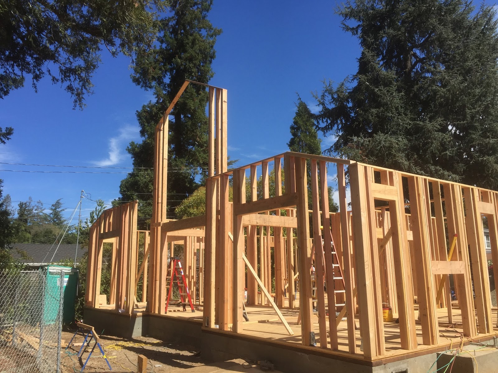
To layout any part of a house here in California, you need to start from the roof and transfer all of the bearing point post back down to the foundation. So you can layout all of the Simpson holdowns you'll need for a continuous load path from the roof to the foundation. In one of the pictures below we laid out 35 Simpson holdowns for the shear walls on the first and second floor and added another 15 Simpson holdowns to the foundation, that were not on the structural plans, for the continuous load path from the roof to the foundation.

Before we start laying out the walls for the house I like to swing a couple of equal length arcs to establish a perpendicular line to an exterior wall that we can use for reference for all of the perpendicular walls in the house.

In the last year  we found that stick framing the studs in the air saves use a lot of time , too many wasted hours trying to lift 2x6 walls with a forklift on the lots we're framing on.

We use to frame like everyone else, by building the walls on the sub floor, however with the holdown rods and plumbing pipes sticking up through the sub floor and all of the 6x PSL beams for headers we stick frame a lot of walls in the air. Only the small walls are still framed on the sub floor.

After I've laid out the first exterior wall my son Erik starts framing immediately. He can usually have most of the house framed by the time I've finished laying out the last wall.




Saturday, April 9, 2016

Sloping Ridges

It's been a while since I've had a sloping ridge in a roof. So, I drew it out in SketchUp to find the angles needed for this equal pitched roof. The first thing that was obvious, I would never be able to draw it out full scale on the jobsite. A sloping ridge is actually hip rafter , so we need to draw out the intersecting eave lines to find the eave angle, or point of intersection. These intersecting eave lines can often be extremely long and require a lot of drawing room on the jobsite.  So, drawing it out in a CAD program is very helpful,  but not always practical either.

The roof has one corner of the building with the typical 90° eave angle. Using any calculator we can find the standard angles for the hip rafter slope angle at an 45° angle from the corner of the building. For the next corner of the roof the eave angle is 120°. Using my RafterTools+ for iPhone we can enter the roof pitch and an eave angle of 120° to find the hip rafter slope angle off the 120° eave angle.

For the sloping ridge we can subtract 90° from the 120° , which leaves us with an Eave angle of 30° that we can use with the RafterTools+ for iPhone to find the slope angle of the sloping ridge.


Here's a drawing of the typical roofs most of us cut and stack here in American homes. The building turns at an 45° angle. The sloping ridge can be calculated using an Eave angle of 45° with the RafterTools+ for iPhone. (135° - 90° = 45°).