This online calculator can be used for unequal pitched roofs, Platonic Solids, Archimedean Solids, Polyhedrons or Parallelogram Roofs. The main objective of the calculator is to find the bevel angles on the top edge of unbacked hip rafter that will produce equal length miter lines on the roof surface.
To calculate the equal length miter line on the roof surface the calculator needs 3 roof slope angles that are perpendicular to the eave/gutter line and 2 eave/deck angles. The bevel angles returned by the calculator are only for one side of the hip rafter. If the roof is an equal sloped roof then the bevel angle can be used on both sides of the hip rafter. However, the bevel angles can be different for hip rafter A and hip rafter B.
Link to the online calculator:
Here's an example print out of the calculations returned for an unequal sloped roof.
Hip Rafter Miter Angles
Hip Rafter Width = 6.00000

Roof Eave Angle for Hip Rafter A = 90.00000
Hip Rafter A Slope Angle = 40.89339
Roof Slope Angle A = 60.00000
Roof Slope Angle B = 45.00000
Plan Angle on Side A = 30.00000
Plan Angle on Side B = 60.00000

Roof Eave Angle for Hip Rafter B = 90.00000
Hip Rafter B Slope Angle = 35.26439
Roof Slope Angle B = 45.00000
Roof Slope Angle C = 45.00000
Plan Angle on Side B = 45.00000
Plan Angle on Side C = 45.00000

Plan Miter Peak Angle = 75.00000
Hip Rafter A Offset Perpendicular = 4.50000
Hip Rafter B Offset Perpendicular = 3.00000

Hip Rafter A Miter Line Peak Plan Angle 1 = 46.22485
Hip Rafter A Miter Line Peak Plan Angle 2 = 43.77515

Hip Rafter B Miter Line Peak Plan Angle 1 = 28.77515
Hip Rafter B Miter Line Peak Plan Angle 2 = 61.22485

Hip Rafter A Miter Line Slope Angle R5P = 30.92761

Hip Rafter B Miter Line Slope Angle R5P = 31.79022

Hip Rafter A R5B = 23.41322

Hip Rafter A R5B = 26.56505

Hip Rafter A - R4P Angle = 38.27203

Hip Rafter B - R4P Angle = 24.15202

Hip Rafter A
Compound Miter Angle and Saw Blade Bevel Angle
Settings for Cutting Material Laying Flat-- Side Face
Hip Rafter A Miter Angle = 40.89339
Hip Rafter A Saw Blade Bevel Angle = 43.77515

Hip Rafter B
Compound Miter Angle and Saw Blade Bevel Angle
Settings for Cutting Material Laying Flat-- Side Face
Hip Rafter B Miter Angle = 35.26439
Hip Rafter B Saw Blade Bevel Angle = 61.22485

Hip Rafter A
Compound Miter Angle and Saw Blade Bevel Angle
Settings for Cutting Material On Top Edge

Hip Rafter A Tetrahedron Angles
D Angle = 49.10661
A Angle = 46.22485
C Angle = 38.27203
E Angle = 30.92761
B Angle = 28.20967
90-D Angle = 40.89339
90-A Angle = 43.77515
90-C Angle = 51.72797
90-E Angle = 59.07239
90-B Angle = 61.79033

Saw Miter Angle = 51.72797
Saw Blade Bevel Angle = 28.20967
Bevel Angle (Compound Angle) = 40.89339

Hip Rafter B
Compound Miter Angle and Saw Blade Bevel Angle
Settings for Cutting Material On Top Edge

Hip Rafter B Tetrahedron Angles
D Angle = 54.73561
A Angle = 28.77515
C Angle = 24.15202
E Angle = 31.79022
B Angle = 16.13617
90-D Angle = 35.26439
90-A Angle = 61.22485
90-C Angle = 65.84798
90-E Angle = 58.20978
90-B Angle = 73.86383

Saw Miter Angle = 65.84798
Saw Blade Bevel Angle = 16.13617
Bevel Angle (Compound Angle) = 35.26439


Calculations for the hip rafter miter & bevel angles:

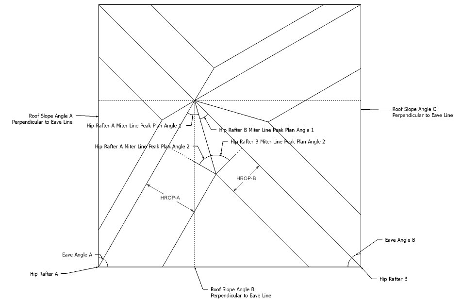
- Calculate the plan angles for both hip rafters using the 3 different roof slope angles.
- There will be 4 plan angles. 2 for each hip rafter. We're interested in plan angles 2 & 3.
- Calculate the plan angle at the peak of the hip rafters in plan view.
- 180 - (plan_angle_h2 + plan_angle_h3)
- Calculate the hip rafter offset perpendicular to the hip rafter run line based on the width of the hip rafter and plan angles.
- HROP_A = ((hip_rafter_width × sin(plan_angle_h2)) ÷ sin(180 - plan_angle_h1 - plan_angle_h2)) × cos(plan_angle_h1)
- HROP_B = ((hip_rafter_width × sin(plan_angle_h3)) sin(180 - plan_angle_h3 - plan_angle_h4)) × cos(plan_angle_h4)
- Calculate the 2 triangles at the peak of the hip rafters in plan view, based off the hip rafter offset perpendicular line to the hip rafter run line.
- After calculating the 2 triangles at the peak, the plan angles at the peak are determined.
- Then we calculate R5B & R5P using the plan angles at the peak.
- R5P_A = arctan(tan(R1_A) × cos(peak_plan_A_angle_1))
- R5P_B = arctan(tan(R1_B) × cos(peak_plan_B_angle_1))
- R5B_A = arctan(tan(R1_A) × cos(plan_angle_h2))
- R5B_B = arctan(tan(R1_B) × cos(plan_angle_h3))
- Calculate the bevel angles on the top edge of the unbacked hip rafters.
- R4P_A = arctan(cos(R1_A) ÷ tan(peak_plan_A_angle_2))
- R4P_B = arctan(cos(R1_B) ÷ tan(peak_plan_B_angle_2))
- Then calculate the saw blade bevel angles for each hip rafter.
- SBBA_A = arctan(cos(R1_A) ÷ tan(R4P_A))
- SBBA_B = arctan(cos(R1_B) ÷ tan(R4P_B))
No comments:
Post a Comment
Note: Only a member of this blog may post a comment.